Welcome NEC visitors!

If you’ve found your way here by taking a note of the web address written on my car at the Classic Motor Show at the NEC this last weekend, then please accept my thanks for spending your precious time at the show taking a look at my humble little project!

For those of you who I spoke to over the weekend, it was great talking to each and every one of you. Although primarily this is a project for my own enjoyment, and to spend some time with my dad, it’s also lovely to share it with all of you and spend time talking about it!

If you’re new here and just want a quick pictorial overview of the progress, you can start off by looking at the Picture Archive, or alternatively you can start at the Introduction and read through the entire saga from the beginning!

I work on this car (usually) one weekend a month, so please do keep checking back regularly for any further updates!

Great news everyone!

Great news everyone! The Dacia Sandero won’t be on the Ford Anglia 105E Owners Club stand in hall 18 at the Lancaster Insurance Classic Motor Show at the NEC on 14-16th November!

But, my car will be!!

A few weeks ago I took a call from the club’s events organisers, looking for a modified vehicle to show off on the stand, and have asked me to take mine.

So, amongst other things that need doing, we have been tidying up some things to get it into a transportable and “presentable” state.

This involves such tasks as…

Fitting of a new windscreen rubber:
New windscreen rubber New windscreen rubber

Some quick & unpolished grinding back of rough welds, filling of holes in the doors, and temporary rust protection of exposed metal with zinc primer:
Temporary rust protection Temporary rust protection Temporary rust protection

Making up a bracket to hold the coolant expansion tank (and more zinc primer):
Expansion tank fitting Temporary rust protection

Fitting of the front bumper, and number plate:
Bumper bracket modifications Front view with bumper and number plate

Fitting a gear lever gaiter:
Gear lever gaiter Gear lever gaiter

So, it’s basically ready to be driven onto the trailer, unloaded and parked up on the stand. So, if you’re visiting the show, come along to hall 18 and take a look in person!

Current view Current view

Braking, suspension, and steering

The first task tackled this time was to cover the pedals & master cylinders, to both make it water-tight, as well as add some strength back to the bulkhead where a little metal had been removed.

Therefore, a box was made up, with a removable lid to aid access, which covers this area. The clutch pipe was also re-routed inside the car, along with the brake pipes, moving it from its previous route which went down the bulkhead right next to the exhaust.

Pedal box cover Pedal box cover Pedal box cover Pedal box cover

Next up was to fit a new set of front shocks & springs, which are now fully adjustable for ride height and damping rate.

Front shocks & springs

When lowering the steering rack to allow the engine to fit in place, the steering geometry was modified from standard, by lowering the rack, “bump steer” was introduced – this is where the wheel as it moves up/down, also rotates as though it is being steered.

In order to overcome the bump steer that was introduced by the need to move the steering rack, it was necessary to move the mounting of the track rod end downwards, to match the downwards move of the steering rack.

This is accomplished by use of a long high tensile suspension bolt, suitable spacers, a rose joint and a length of hexagonal bar, with the correct threads tapped.

Steering correction

Moving underneath the car, the remaining chassis outrigger/jacking point was replaced – not with capabilities for the standard jack, but instead utilising some box section, which will give a perfect location for a more commonly available scissor jack, like is found with more modern cars.

Chassis welding

Additionally, the rear end of the driver’s side sills were finished, which mostly concludes the remaining structural welding that was required underneath.

Ace Update

So, I’ve concluded that I suck at taking photos and keeping this updated!

I’ve had a couple of trips to my dad’s since the last update, and have failed to take any photos!

The first trip involved removing the engine/gearbox, and sorting out a couple of small oil leaks, which came from the lack of gaskets on the turbo oil return pipes. Whilst the engine was out, a new sump pan was also fitted, to replace the corroded one that was on there.

A little more tidying was done of fuel/vacuum pipes coming through the bulkhead, these now are plugged in on either side of the bulkhead to a small length of copper pipe which is soldered to the bulkhead. Quick to remove the pipes from inside or outside, and a water-tight way to get through the bulkhead.

Also, whilst the engine was out, the area we had cut away from the bulkhead to facilitate the water manifold and radiator hoses was looked at and mostly replaced, and we now have just a small removable panel to make and fit.

The second trip was more eventful, as we decided to take a day off from working on the car, to go and show it off at the annual Anglias At The Ace meet, organised by 105speed. The Friday evening was spent tidying up to make it somewhat “presentable” – it had a wipe down with a damp sponge and dried off with a towel, the passenger seat was re-fitted, the remaining cables under the dash were tidied with a few cable ties, and I even screwed in the glove box lid and ashtray/heater control panel!

Saturday morning, we loaded up onto the trailer, and headed off for the Ace Cafe, my dad towing my Anglia, and me driving his, and arrived to a mostly empty car park, being about the 8th Anglia to arrive. We unloaded the trailer, and parked up, and awaited the rest of the arrivals.

The day didn’t disappoint, with 54 Anglias all together, and I had a great opportunity to speak to many people about the car.

IMG_5643 IMG_5644 IMG_5645 IMG_5647 IMG_5648 IMG_5649 IMG_5651 IMG_5652 IMG_5653

And our two cars, including my dad posing with his cup of coffee!

2014-07-19 13.38.05 IMG_5646

On our way back, we had a radiator blow out on the Shogun, which left us stranded at the side of the A406 for over 8 hours awaiting a truck to be provided that could recover the Shogun + trailer back home! So, that was quite a bad end to an otherwise great day!

I hope that normal service will resume next update, and I’ll try to take some more photos!

Securing things

First task was to remove the final bit of the chassis where it had started to go rotten – the rear cross member.

This involved cutting out the existing metal, and we decided to graft in a 50x50x3mm box section – which will be way stronger than the original box section. I may well add a jacking point/towing eye to this in the future. This was grafted onto the existing chassis legs (which are no longer load bearing due to the changes in suspension), and brought round to meet up with the original rear panel.

Rear chassis box section Rear chassis box section Rear chassis box section Rear chassis box section

With the rear valance back in place – no visual differences from the rear.

Rear valance

Moving forwards, the items that live in the boot are secured down – the battery is tied down, the straps for the fuel tank are secured to the floor, the vacuum tank for the servos is secured (you can just see a shiny strap in the first photo) and the charge cooler pump/reservoir are secured, as is the charcoal canister which prevents petrol fumes from being smelt via the tank breather.

Battery tie down Charge cooler reservoir and carbon canister

Moving forward again, and into the car this time. A new transmission tunnel top was fabricated and welded into place, to cover the 200SX gearbox. Additionally, all the fuel and brake pipes, as well as the main battery cable which run through the car were secured into place. The chargecooler pipes and vacuum pipe for the vacuum tank still need to be secured in their final positions once I get some suitable clips of the correct size for them.

Transmission tunnel Pipe clips

WordPress 3.9 Breaks WP-United Theme Integration

A small break from the traditional content here (but, if you’re a new visitor, please take a look at what I’m currently spending all my money on!)

As part of my role as website administrator for the Ford Anglia 105E Owners Club, I have to deal with updates to the software that runs the site – this namely is WordPress and phpBB.

Having had an existing phpBB forum, and introducing WordPress as the front-end, I wanted to merge the two, both in look & feel, and users, to provide a seamless transition between the forum and website.

To this end, I have utilised WP-United – however, the recent update to WordPress 3.9 has broken this integration, and when the Theme Integration is enabled in “phpBB in WordPress” mode, attempting to browse to any phpBB page results in a plain white screen.

I’ll update this as I find any more information – but wanted to get something out there onto the web so that anyone searching will find, and hopefully any WP-United users can find a solution.

Else, I’ll be looking back towards utilising something like bbPress… although I still don’t think it’s as good for forums as phpBB!

Loomed up

I didn’t put up any photos of the front end last time out, and although the wiring was done, it wasn’t tidy, so, spent some time tidying up the remainder of the wiring, both on the front end, and under the dash, taping up any loose bit of wire! Over all, I must have used well over a roll and a half of insulating tape!

IMG_5590

Also, the key locks to secure the flip front in place, and some lengths of chain were added to limit how much it opens – this gives good access across to the top of the engine, without putting the front too close to the floor. The wiring was secured by fibreglassing some cable ties onto the inside of the front, which create loops to put a further cable tie through – meaning if I need to remove the wiring loom (for example for painting), I can easily do so, and re-attach it again at a later date.

IMG_5584 IMG_5588

With the dash in finally (and the wiring loomed up, as mentioned earlier), I thought I’d take a photo of the gauges working – I’ve got about 1/8th tank of fuel, and it’s ticking over nicely at just under 1250rpm.

IMG_5591

Additionally, some welding was tackled underneath.

And finally…

Indicative gauges are exhausting

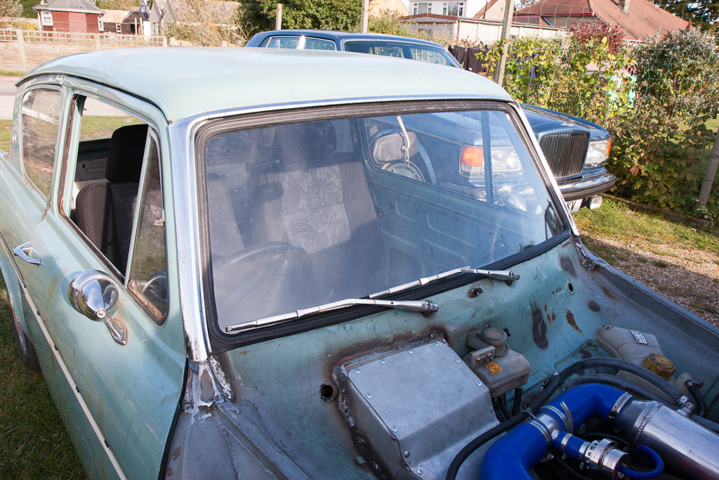
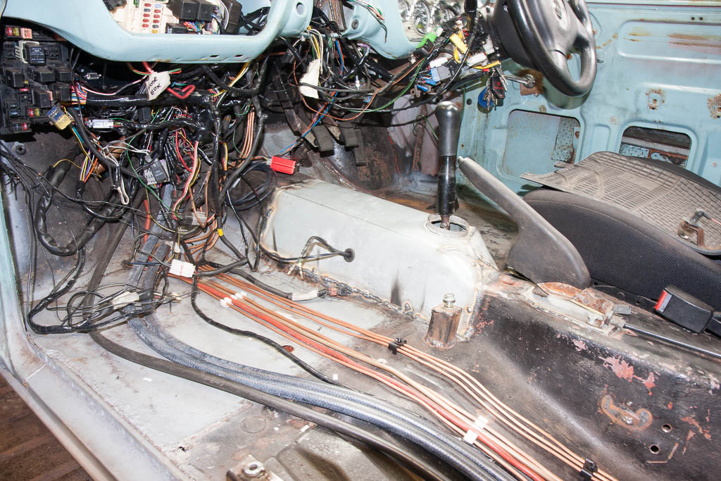
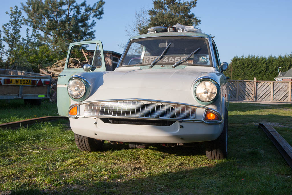
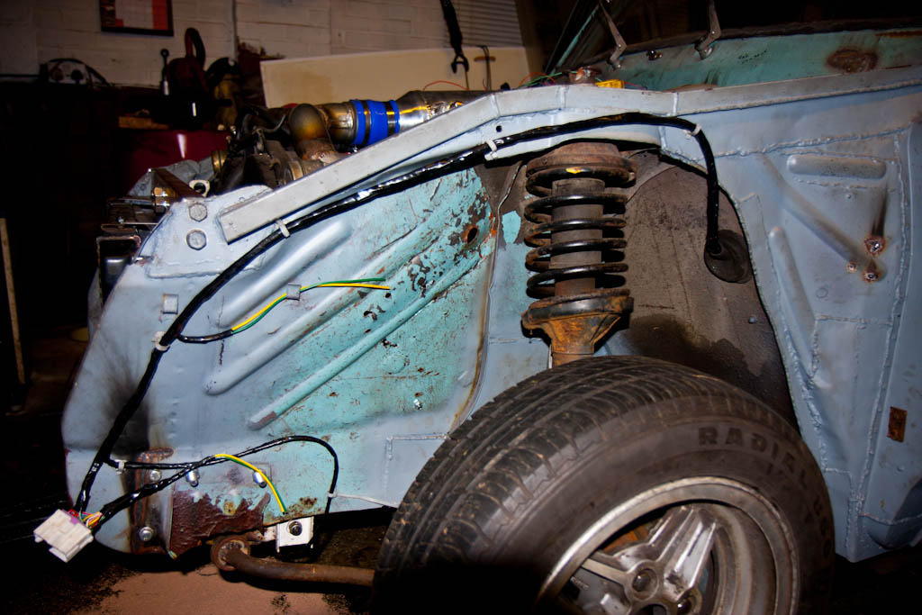
Following on from last time, I have now completed the wiring to the front end, with indicators, side repeaters and headlights now all wired up and working.

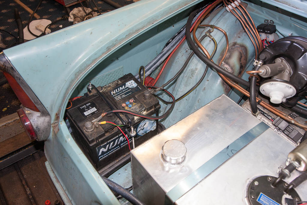
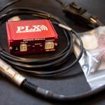
When browsing forums, I found someone who was selling a MAP-ECU 2 – the next version of the MAP-ECU which I already have installed (the little box of tricks that allows removal of the MAF sensor) – the newer model adds a few new features – ignition timing control, two switchable maps, electronic boost control, air/fuel ratio adjustment, fuel cut removal, speed cut removal, and launch control.

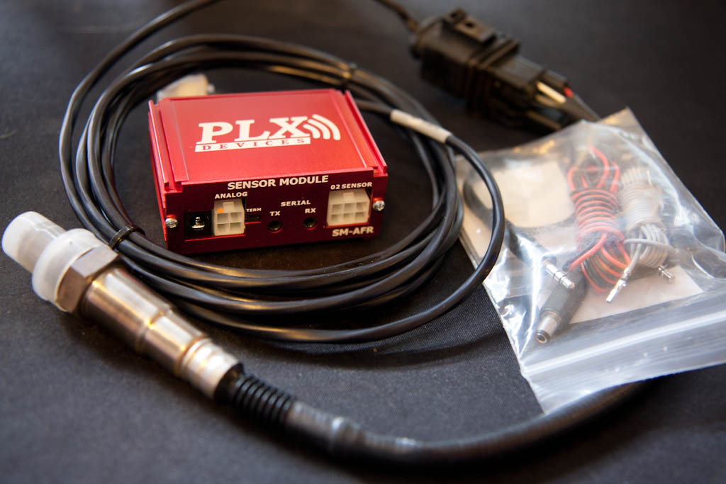
I paired this with a wideband O2 sensor/controller, which provides a very accurate air/fuel ratio to the MAP-ECU2, as well as a simulated narrowband output to the stock ECU.

PLX SM-AFR PLX SM-AFR

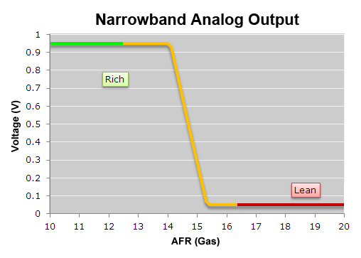
A standard narrowband O2 sensor as fitted to most vehicles operates by switching the output between 0v and 1v when the air/fuel ratio (AFR) goes either side of the stoichiometric point – the point at where all fuel is evenly burned with all of the available air – with petrol this is an AFR of 14.7, or lambda 1.00

The narrowband O2 sensor is used by the ECU to adjust the amount of fuel – an input value of 0v means “add more fuel” and an input value of 1v is “less fuel” – under normal use, the standard ECU will adjust the fuelling to ensure that the input voltage from the O2 sensor is rapidly fluctuating between 0v and 1v – this keeps the engine around lambda 1.00

This is shown by the following graph (graphs taken from the PLX website)

AFR Narrowband Output

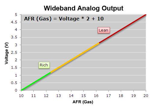
The wideband O2 sensor gives a voltage output which is directly related to the AFR, typically from 0v to 5v. The PLX SM-AFR I have provides a linear output and can show the AFR from 10:1 to 20:1 (lambda 0.68 to 1.36), as demonstrated by the following graph (again, taken from the PLX website)

AFR Wideband Output (PLX SM-AFR)

When running under load, you may not want an AFR of 14.7 – you may want to run richer (more fuel), say at an AFR of 12 – with a narrowband O2 sensor, you have no way of telling what your AFR is, only that it’s “rich” or “lean”. With the wideband, I can monitor this via the MAP-ECU2, and adjust the fuelling accordingly to reach that target.

The MAP-ECU2 came from another VR-4, and the configuration that’s on it is much better than the one that came on the original MAP-ECU I had (which also came from a VR-4) – the new one idles even better, and the lag that I had when pressing the throttle has disappeared. Even just this change is worth the money spent on it, as it puts it a lot closer to what’s needed, which will hopefully reduce the need for an immediate expensive tuning session!

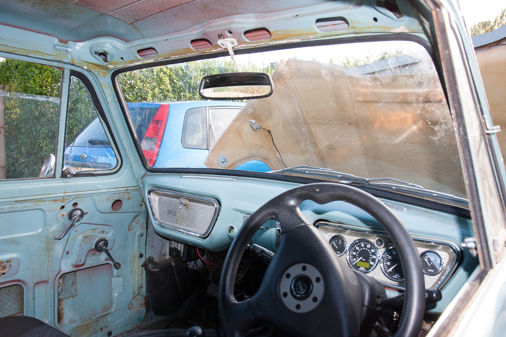
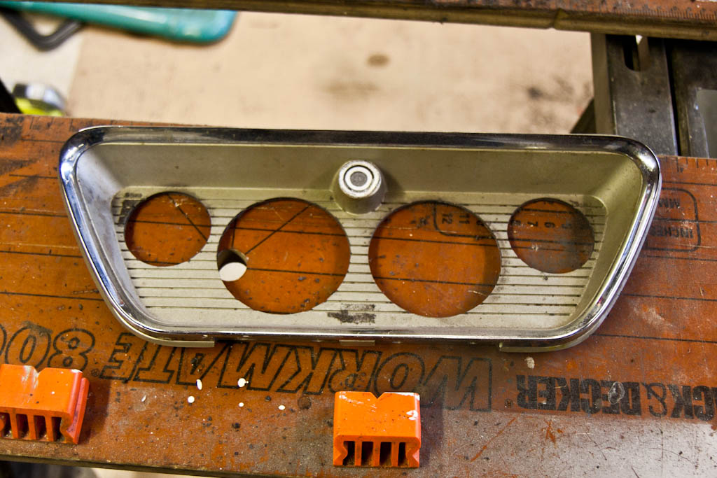
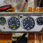
In addition to this, I received a nice package from ETB Instruments consisting of a 52mm fuel gauge, a 52mm temperature gauge, an 80mm electronic programmable speedometer and an 80mm tachometer.

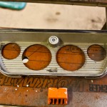
I am fitting these to a glove box lid, so I started by marking up and drilling out the necessary mounting holes:

Dial panel

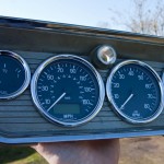
It was then time to fit the dials, and wire them up to a connector plug to allow easy removal from the rest of the wiring loom.

ETB Instruments ETB Instruments

The new speedometer is programmable so it can be used with a wide variety of speed sensors and can be programmed to suit your wheel/tyres, diff and gearbox – and any changes to any of these the speedometer can be reprogrammed very easily – if I had a mechanical speedometer, I’d need to send it off for recalibration if I ever made any changes.

It also provides the following features:
2 trip counters
0-xxmph time (comes as default set as 0-60mph)
1/4 mile time
Max speed recall
In built indicator lamps

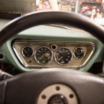
I also fitted a 3-spoke Momo steering wheel from an Evo 6, which is slightly smaller than the standard wheel from the VR-4, and placed the dials in place (but the glove box lid is not secured to the dash properly yet)

ETB Instruments

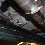
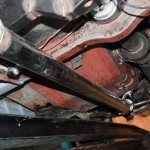
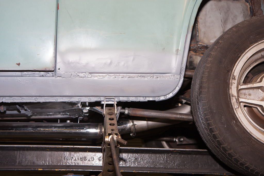
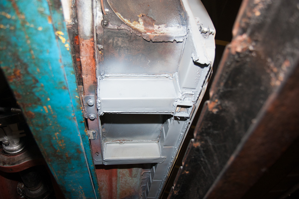
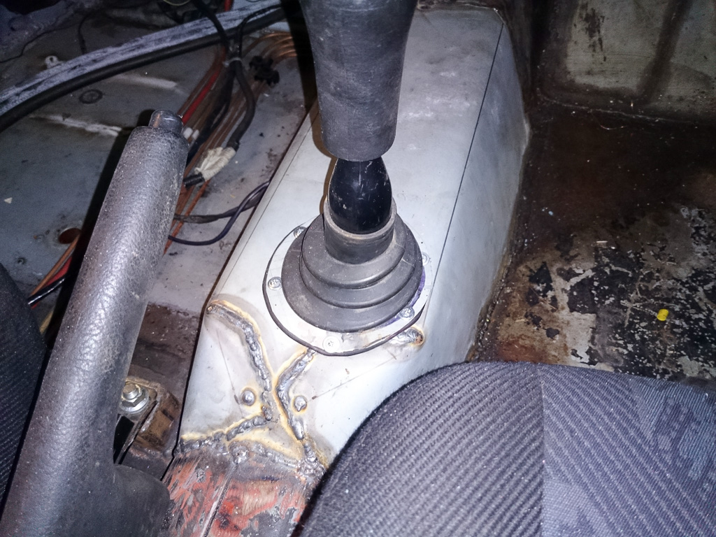
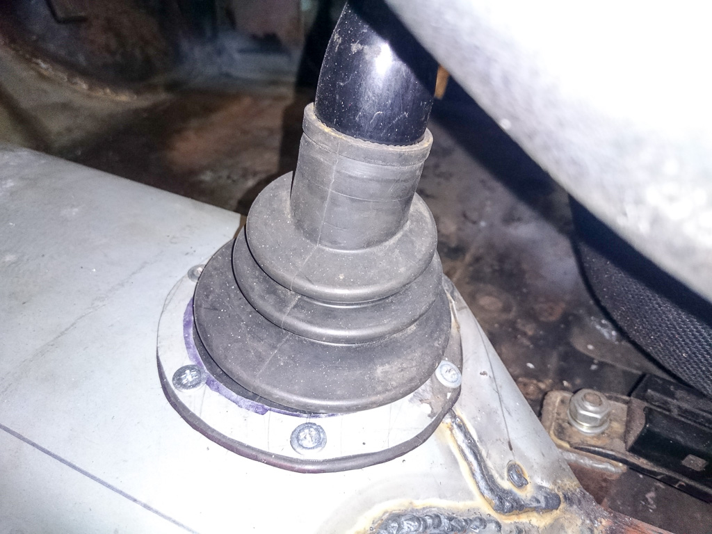
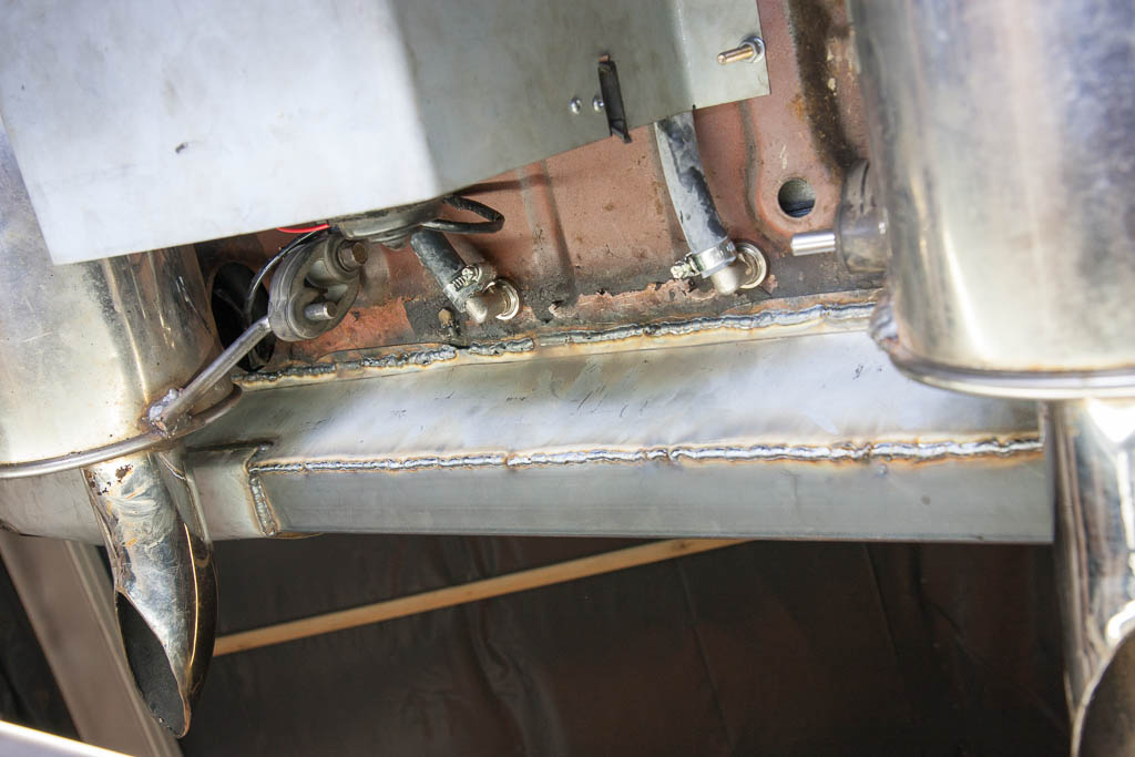
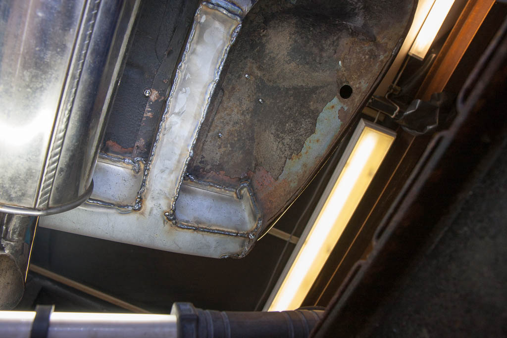
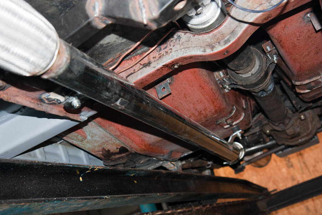
Whilst I was fiddling with wiring and electronics, my dad was concentrating on welding, and we now have the passenger side rear suspension mount and floor completed, as well as the exhausts now properly mounted on cotton reel mounts, rather than suspended from bits of electrical wire.

IMG_5559 IMG_5558

Flipping front end

I start off this time with some braking news…

This just in: Capri 2.8 vented discs fitted!

Capri 2.8 vented discs

Next up, a one-piece fibreglass front from Team de Ville. A small amount of trimming was required to make it fit, as it comes supplied with the lips down the back edge of the wings which tuck around the A pillar behind the front of the doors. As I wanted to be able to flip this open without needing to have the doors open, these lips were removed.

Fibreglass flip front Fibreglass flip front

And then, with grill, headlights and surrounds fitted. Just left to fit the bumper, and indicators, and then do the wiring.

Fibreglass flip front

It’s finally looking more like a car!!

Lights, Camera, Picture

More wiring! More headaches!

Other than general tidying and removal of extra length, the main thing that needs sorting now wiring wise is for about the only electrical systems left on the vehicle – lights, horn and wiper!

So – onto those then! Wiring for horn + front lights was identified, tidied, routed, loomed and affixed:

Front light wiring

With a nice connector plug ready to make removal of the fibreglass flip front (which has been ordered, awaiting delivery) as simple as possible.

And the rear lights were dug out of storage, bulbs checked and replaced where necessary, and wired up, including tidying up and re-looming the run of wires to the rear:

Rear lights