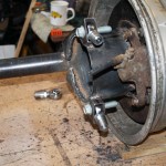
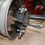
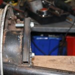
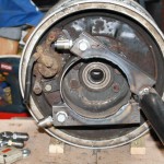
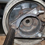
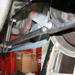
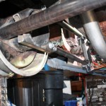
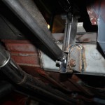
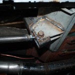
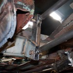
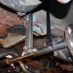
Next up on the axle, is the trailing arms. There will be 2 trailing arms on each side, which will prevent the axle from twisting under braking or acceleration.
First up, is to fabricate the mounts on the axle. Utilising some heavy box section, a mount is added to the top and bottom on each side, and fitted with heavy duty M14 rose joints.
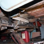
With the axle end done and offered up to the car, the body end of the trailing arms take shape. The original rotten spring hangers are removed, and another bit of heavy box section is tacked into place, as well as the trailing arms fabricated at the correct length. The trailing arms are made equal in length, and have one left-handed and one right-handed thread rose joint attached – this will allow infinitely fine adjustment to the positioning of the axle within the wheel arch without having to remove it from the car.
Additional bracing begins being added to the mounts and the floor/box section. There is still more to be finished.
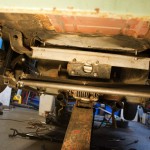
In order to set the ride height and calculate length of shocks/springs needed, a temporary solution is tacked into place – a length of box section and couple of temporary brackets.
The trailing arms will prevent the axle from moving forwards/backwards, but will not prevent it from moving left/right. To prevent this movement, a panhard bar is added. This attaches to the axle on one side, and to the body on the other.
A heavy duty bracket is fabricated and attached to the floor – this wraps around the chassis rail for additional strength.
The panhard, like the trailing arms, is fitted with a left-hand and a right-hand threaded heavy duty rose joint, which will allow fine adjustment of the left/right position of the axle without removing anything from the car.
The diff was also lifted back into the rough location, a length of angle has been added to the mount to move the load closer to the edge of the boot floor, closer to the chassis rails where there is more strength.
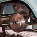
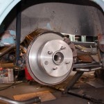
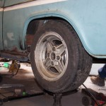
Finally – a wheel with tyre (currently 185/60/13) is fitted to see what it would look like.

