Following on from last time, I have now completed the wiring to the front end, with indicators, side repeaters and headlights now all wired up and working.
When browsing forums, I found someone who was selling a MAP-ECU 2 – the next version of the MAP-ECU which I already have installed (the little box of tricks that allows removal of the MAF sensor) – the newer model adds a few new features – ignition timing control, two switchable maps, electronic boost control, air/fuel ratio adjustment, fuel cut removal, speed cut removal, and launch control.
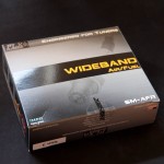
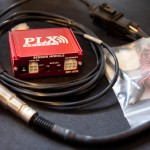
I paired this with a wideband O2 sensor/controller, which provides a very accurate air/fuel ratio to the MAP-ECU2, as well as a simulated narrowband output to the stock ECU.
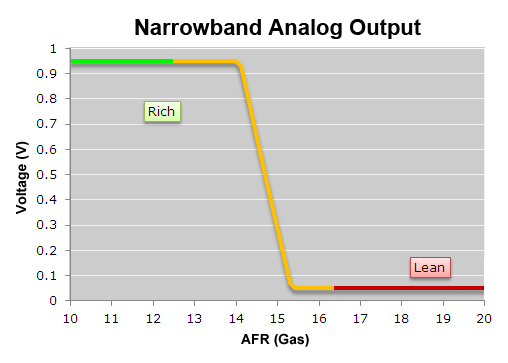
A standard narrowband O2 sensor as fitted to most vehicles operates by switching the output between 0v and 1v when the air/fuel ratio (AFR) goes either side of the stoichiometric point – the point at where all fuel is evenly burned with all of the available air – with petrol this is an AFR of 14.7, or lambda 1.00
The narrowband O2 sensor is used by the ECU to adjust the amount of fuel – an input value of 0v means “add more fuel” and an input value of 1v is “less fuel” – under normal use, the standard ECU will adjust the fuelling to ensure that the input voltage from the O2 sensor is rapidly fluctuating between 0v and 1v – this keeps the engine around lambda 1.00
This is shown by the following graph (graphs taken from the PLX website)
The wideband O2 sensor gives a voltage output which is directly related to the AFR, typically from 0v to 5v. The PLX SM-AFR I have provides a linear output and can show the AFR from 10:1 to 20:1 (lambda 0.68 to 1.36), as demonstrated by the following graph (again, taken from the PLX website)
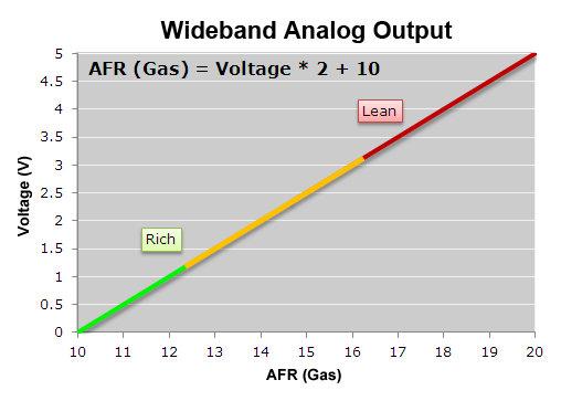
When running under load, you may not want an AFR of 14.7 – you may want to run richer (more fuel), say at an AFR of 12 – with a narrowband O2 sensor, you have no way of telling what your AFR is, only that it’s “rich” or “lean”. With the wideband, I can monitor this via the MAP-ECU2, and adjust the fuelling accordingly to reach that target.
The MAP-ECU2 came from another VR-4, and the configuration that’s on it is much better than the one that came on the original MAP-ECU I had (which also came from a VR-4) – the new one idles even better, and the lag that I had when pressing the throttle has disappeared. Even just this change is worth the money spent on it, as it puts it a lot closer to what’s needed, which will hopefully reduce the need for an immediate expensive tuning session!
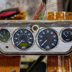
In addition to this, I received a nice package from ETB Instruments consisting of a 52mm fuel gauge, a 52mm temperature gauge, an 80mm electronic programmable speedometer and an 80mm tachometer.
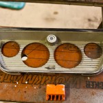
I am fitting these to a glove box lid, so I started by marking up and drilling out the necessary mounting holes:
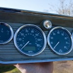
It was then time to fit the dials, and wire them up to a connector plug to allow easy removal from the rest of the wiring loom.
The new speedometer is programmable so it can be used with a wide variety of speed sensors and can be programmed to suit your wheel/tyres, diff and gearbox – and any changes to any of these the speedometer can be reprogrammed very easily – if I had a mechanical speedometer, I’d need to send it off for recalibration if I ever made any changes.
It also provides the following features:
2 trip counters
0-xxmph time (comes as default set as 0-60mph)
1/4 mile time
Max speed recall
In built indicator lamps
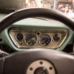
I also fitted a 3-spoke Momo steering wheel from an Evo 6, which is slightly smaller than the standard wheel from the VR-4, and placed the dials in place (but the glove box lid is not secured to the dash properly yet)
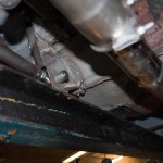
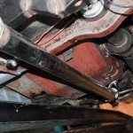
Whilst I was fiddling with wiring and electronics, my dad was concentrating on welding, and we now have the passenger side rear suspension mount and floor completed, as well as the exhausts now properly mounted on cotton reel mounts, rather than suspended from bits of electrical wire.

