First off, I know it’s been a few months since any updates – I’ve not fallen off the face of the planet! The weekends have just fallen quite badly – with the likes of Christmas and other events meaning that time spent on the car has been reduced.
Some of this time has been spent in re-wiring the engine (again) – this time, using quick-release connectors, which will be located in a much better place than they currently are. The current connectors are all tucked down between the engine and the bulkhead, and have prevented us from making up the panel to seal off the bulkhead again.
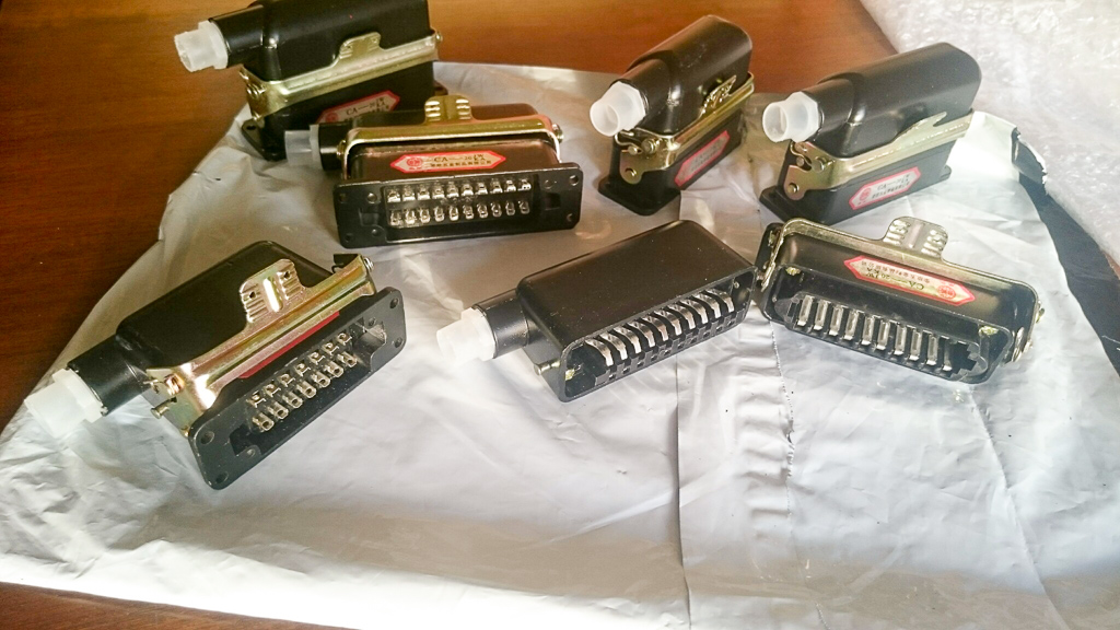
These are the connectors I’m now using – have worked out (after buying them) that 2x 20 pin connectors is enough to do all of the engine wiring (but no harm in having some extras)
It had always been a plan of mine to have fully independent suspension on the back of the car, because it allows the greatest amount of adjustment, which will be critical to get the handling just how I want it.
However, my dad didn’t initially want to go fully independent, and so we came to an agreement on the De-Dion setup. The plan then was to drive it around for a while, and then redesign the suspension later.
However, he has since changed his mind, and come round to my way of thinking, so we’ve now started to replace the De-Dion with fully independent – whilst still maintaining the majority of the work on the suspension we’ve already done.
So, the plan is to replace the large, solid tube between the two hubs, and the panhard bar, with more links – we will need upper and lower, to prevent the wheels from folding in on themselves, or falling outwards (like the DeLorean from Back To The Future Part II). There will be 3 of these on either side – 1 top, 2 bottom, which will also allow for a control of toe.
The existing twin trailing arms will remain, and these will prevent the wheels from moving forwards/backwards, as well as preventing any rotational force applied by braking or acceleration.
The following diagram should hopefully explain this better, and this will be the basis of our design. (Red is the existing trailing arms, green will be the new arms we need to make)
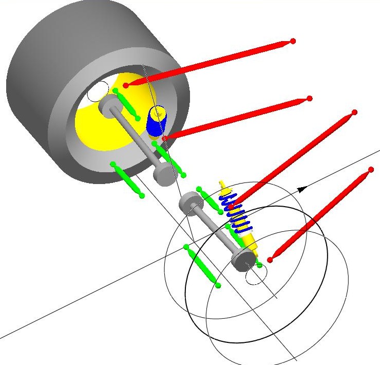
Found on the SusProg3D site.
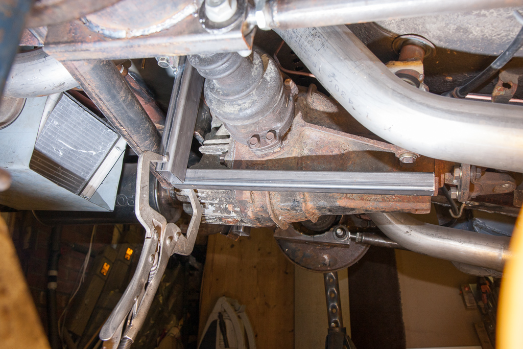
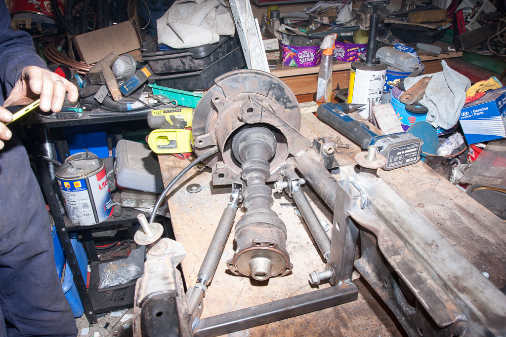
The first step is to add a frame around the diff, which will form the inner mounts of the suspension arms.

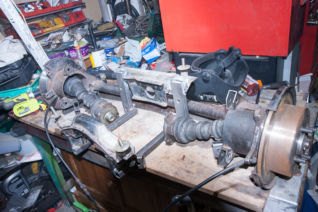
With the basic positioning sorted with it on the car, and the parts tacked together, we then removed the current axle, and put it all onto the bench for fully welding up all the parts for the frame that becomes part of the diff carrier.

Whilst it was still bolted to the car, we tacked on the lower brackets for the wheel end of the suspension arms – these will be fully welded on when we are perfectly happy with their position.
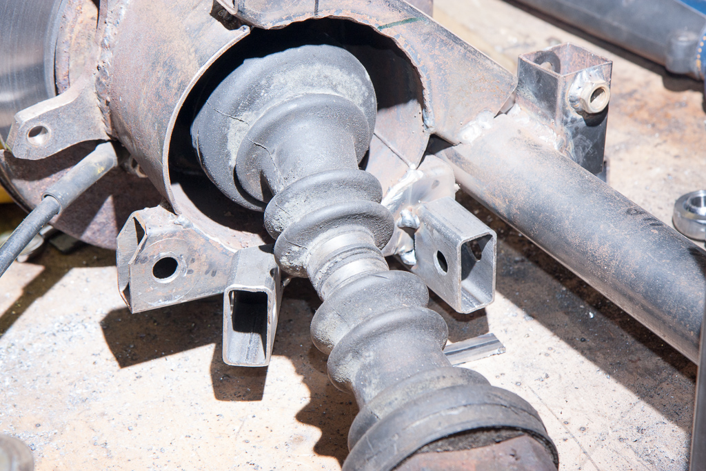
Putting it all together on the bench, we position the existing axle with the modified diff carrier, and begin to make up the suspension arms.
By doing it this way – until we are happy with the positioning, we don’t have to cut through the De-Dion tube, so we could potentially bolt it back up to the car without affecting the current suspension setup! This is one of the reasons we prototype in the way we do – functional, usable, but not necessarily completed immediately – whilst yes, it took us some time to make the De-Dion axle, it allowed us to get it rolling under its own power, gave us the ability to position the diff, exhausts, trailing arms etc and build around them, but still give us the option to change things later – or, if we’re happy with what we prototyped, we will go back to it and finish it off to a high standard.