Front suspension polybushing

Just a quick update this time round! Have been doing some work on the front suspension, replacing the existing rubber bushes on the track control arms with new polyurethane one. The old bushes had so much play in them, the front suspension geometry was all over the place. With the new bushes, the front end has no excess play, and the tracking can be set accordingly.

Also spent some more time on wiring – still a fair bit to tidy up, and every little helps, even if it doesn’t look like there’s been any progress!

A lesson on Blow Off Valves

Last time, I managed to get as far as hooking up a couple of hoses from the chargecooler to the bulkhead.

So the task this time was to complete the chargecooler circuit, which involved running pipework to the rear of the car, through the boot floor and to the radiator box, which still needed a bit more to easily hook up the pipes.

Chargecooler pipework

Forgot to take any images, but the chargecooler system is now completely plumbed up, including an old coolant header tank as a reservoir, and the pump is hooked up to the trigger for the fuel pump, so is running whenever the ignition is on. An adjustable temperature-activated switch is still to be installed, which will switch the fan on when the coolant temperature in the chargecooler circuit gets to a specific temperature – which is yet to be decided!

Having had a bit of temporary pipe on the inlet, which had to be bunged up with an old injector, it was time to change this to a proper bit of pipe, with the correct outlets on it – such as for a blow-off valve (BOV – also known as a dump valve, or diverter valve)

The job of the BOV is to relieve excess pressure in the intake when the throttle is closed.

When you accelerate a turbo’d engine, the exhaust gasses drive the turbine on the turbo, which in turn drives the compressor on the turbo, which takes air at atmospheric pressure, and compresses it to a higher pressure – the standard TD-03 turbos on the 6A13TT will compress the air to about 10 PSI above atmospheric pressure (which is 14.5 PSI). Once compressed, there are more oxygen molecules in a given volume, and this allows more fuel to be introduced, which creates a bigger bang in the engine, and therefore more power (and more exhaust gasses) – the process repeats over and over.

With the throttle body open, this compressed air will get forced into the cylinders in the engine. When you stop accelerating, you close the throttle body, and there is now nowhere for this compressed air to go. The turbo continues spinning for a small amount of time after you stop accelerating, which continues to compress the incoming air – trying to add to the compressed air already in the inlet pipework between the turbo and the throttle body.

If there were no BOV, then this compressed air would try to equalise pressure by the easiest possible route – which would be to try to go back out through the compressor of the turbo – this can cause the compressor of the turbo to be attempting to compress the air, whilst the already compressed air is trying to come back the other way – causing the compressor wheel (and, because they are linked, the turbine wheel) to stop turning, or even attempt to turn the opposite way (fighting against the exhaust gasses still trying to turn the turbine the correct way) – this can cause a “fluttering” noise. This is also known as compressor surge.

You can hear it a bit in my previous videos, but the following video also shows it off well:

To prevent this, the BOV is installed in the inlet pipework after the turbo, and before the throttle body. This is a large valve, operated by a diaphragm, which has a spring inside to hold it closed, as well as a vacuum/pressure pipe which is attached to the manifold (after the throttle body) – when the turbo is producing a positive pressure in the intake manifold, this pressure also assists in keeping the BOV closed by pushing against the diaphragm. Spring + compressed air pressure on one side of the diaphragm is a larger force than the compressed air pressure in the intake pipework.

When you close the throttle body, the intake manifold then goes into a vacuum, which pulls against the diaphragm – this vacuum, combined with the positive pressure of the intake pipework, allows the valve to open – giving the compressed air in the intake pipework an easy route to escape, without going back through the turbo compressor wheel.

On most production cars, this is routed back into the intake *before* the turbo – a recirculating valve. Especially where a MAF (Mass Airflow Sensor) is used, where the air has already been accounted for by the engine ECU. It is less of an issue where a MAP (Manifold Absolute Pressure) sensor is in use, because this air has not been accounted for yet by the ECU.

The Anglia has no pipework before the turbos to route this air to – therefore the BOV used is a Vent To Atmosphere (VTA) one. A VTA BOV is what gives the “pssssstthhhh” noise that you associate with a turbo car.

Intake pipework completed

(the picture was taken before I’d attached the small blue vacuum pipe to the BOV – this is what attaches to the manifold)

With the inlet pipework and BOV now correctly hooked up – there is no loss of pressure in the inlet any more, and a small touch of the throttle causes the boost to climb quite quickly! It’ll be fun to drive…!

You gotta speed it up, and then you gotta slow it down

I began last time to fit the brakes to the car, and the most of the work on the car this time round was in completing the braking system.

This involved running 2x lines from the master cylinder to the servos in the boot, and from the servos, out to each of the 4 wheels.

IMG_5024 IMG_5032

Taking cues from modern vehicles, we are installing dual circuits, splitting the circuits diagonally across the car.

One circuit is Left Front/Right Rear, the other is Right Front/Left Rear. By doing this, should there be an issue with one circuit, the other circuit should still be able to provide braking force, and by diagonally splitting the circuits, the braking is more balanced during these situations.

As I am using a combination of Escort calipers on the front, and 200SX calipers on the rear, I can’t buy a flexible brake hose kit off the shelf, so took another trip to Hosequip where they made up some custom braided pipes with our choice of ends to suit our needs.

IMG_5034 IMG_5036

The chargecooler was also put into place, and have begun to plumb it in.

IMG_5027 IMG_5028

We also spent some time moving my dad’s ramp from one side of the garage to the other – with the new roof we fitted last year, this now allows us to get the car much higher off the ground – and can now stand underneath it, rather than having to crawl under it! This will help when we do the remaining welding under the car which will need to be done prior to thinking about putting it on the road.

The credit card gets a hammering

This is by far the most expensive update I’ve put up throughout the history of this project!

The first item on the credit card statement is a proper fuel tank. With the changes to the axle and the dual exhausts, the standard fuel tank was removed a while back. Additionally, I had a couple of brand new in-tank fuel pumps, so it seemed silly to not utilise them. Plus, with the car starting and running now, it seemed a sensible time to replace the bucket, and we can now keep it fuelled up so it’s easier for my dad to move it around should he need to.

I contacted Alloy Racing Fabrications who were able to make me a nice shiny alloy tank to my exact specifications.

New fuel tank from Alloy Racing Fabrications New fuel tank from Alloy Racing Fabrications

The pump housing is the same as was used in the bucket, but the pump itself has been replaced with an uprated ProDrive pump as fitted to the ProDrive Imprezas – will definitely supply plenty of fuel to the engine.

The next line on my credit card bill is for brakes – a new set of M16 calipers to bolt up to the Escort front struts. We also got hold of a couple more 13″ tyres and fitted them to the remaining 4-spoke alloys, so it’s now got a full set of matching wheels.

New M16 calipers Full set of 4-spoke alloys

The VR4 engine usually has an air-air intercooler to cool the compressed air coming from the turbos before it goes into the intake. This is placed at the front of the car and the ambient air moving over surface of the intercooler cools down the warmer air passing over the internals of the intercooler.

Whilst I had never planned to fit an intercooler due to space constraints, I decided on instead fitting an air-water chargecooler.

The chargecooler works with a similar process to the standard engine cooling – a liquid coolant is pumped through the chargecooler, and then passes through a radiator, which removes the heat from the water.

A chargecooler allows fitment in a tighter space than an air-air intercooler, and doesn’t require the lengths of large-diameter air pipework between the turbo and the inlet. All it requires is a couple of much smaller diameter coolant pipes.

There are a number of styles of chargecoolers available, but I decided on a barrel-style, which will sit in the current inlet tract, replacing the pipe running across the top of the engine directly after the Y piece.

Chargecooler Chargecooler Internals

Air passes through the large openings in each end, and water passes through the two smaller openings on the side.

With space tight at the front, and not wishing to dump the heat from the chargecooler in front of the engine coolant radiator, I have decided to mount the other part of the chargecooler at the back of the car. Utilising a heater matrix element, I have begun to make up a box which will sit under the car, in the position of the existing fuel tank, between the two exhausts. This will primarily work by just forcing air through the core, but a fan is also added to aid cooling when at low speeds or when stationary, which will activate based on the temperature of the coolant within the chargecooler system, completely independent to the engine coolant system.

Chargecooler box Chargecooler box

Finally, the trailing arm mount on the driver’s side for the rear suspension was fully boxed in and tied into the chassis. We will repeat this for the passenger side.

Rear suspension mount boxed in

And finally, just because… another quick video:

Keep cool and wire on

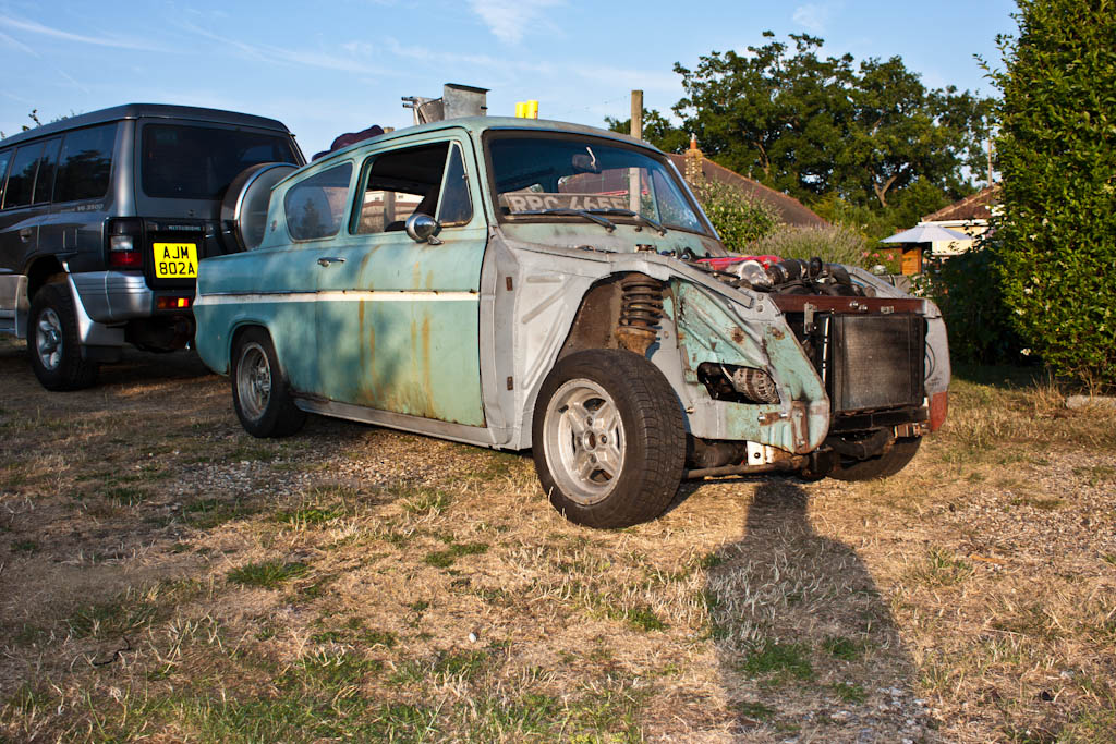
Now that the car can drive again, my dad has been able to move it around when he needs access to his workshop. However, doing so means starting the engine from cold each time, and something hasn’t been quite right with it, it’s not been wanting to fire up first time. Once it’s going, and it’s got a little warmth, it will restart fine – but it’s also been running exceptionally rich, dumping in lots and lots of fuel.

Something didn’t seem quite right, so it was time to don the diagnostic hat, and see what didn’t look right.

The VR4’s ECU has a diagnostic connector, physically similar to OBD (On-Board Diagnostics), but uses Mitsubishi’s own communication protocol. Luckily, someone has figured this out, and for just $25, you can purchase EvoScan, which allows you to read data from the engine ECU. A small price to pay for the awesome features you get. You have probably seen a shot of this running on the laptop in a previous video, along with the MAP-CAL software for the MAP-ECU unit.

Taking a look at all of the various sensors you can read, I noticed a couple of things were odd. Firstly, the TPS (Throttle Position Sensor) value was a little off – with the throttle fully closed, the value should read approximately 11.5-12.5%, and with the throttle fully open, around 96%. With the throttle closed, this was reading around 15%.

Adjusting this is quite a simple process, thankfully. Firstly, place a 0.65mm feeler gauge between the stop and the butterfly wheel to partially open the throttle. Then, remove the connector plug, loosen the two bolts holding the TPS sensor, and rotate the sensor until the point where you lose connectivity between the bottom two pins – these are the pins for the Idle Position Switch – when there’s continuity between the two, the throttle is fully closed.

With this adjusted, the TPS reading in EvoScan was a more healthy 12.2%

I also noticed that the Coolant Temperature Sensor was reading -59 degrees C. I know it’s been a cold June, but not quite that cold!

Checking the sensor, we found no continuity between the sensor ground and the relevant sensor ground pin on the ECU. Tracing back the wiring, it seems we’d omitted the ground wire – if that’s our only wiring issue so far with the amount we’ve removed and chopped, then I’m not too displeased!

All the other sensors looked OK, no readings that jumped out as being wildly inaccurate.

The last thing to look at was on the MAP-ECU. On this, you also specify the throttle position values for fully closed and fully open – as I’d adjusted the throttle position sensor, I had to resample the values for the MAP-ECU configuration.

With all of this checked, we tried to fire up the engine – it now bursts into life on the first turn of the key, and seems to be running slightly less rich than it was – it now knows that the coolant is at the correct temperature, so isn’t applying quite such a high cold start enrichment (it adds more fuel when cold)

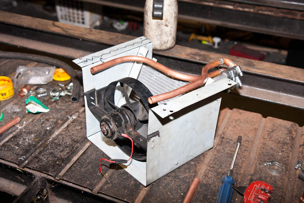
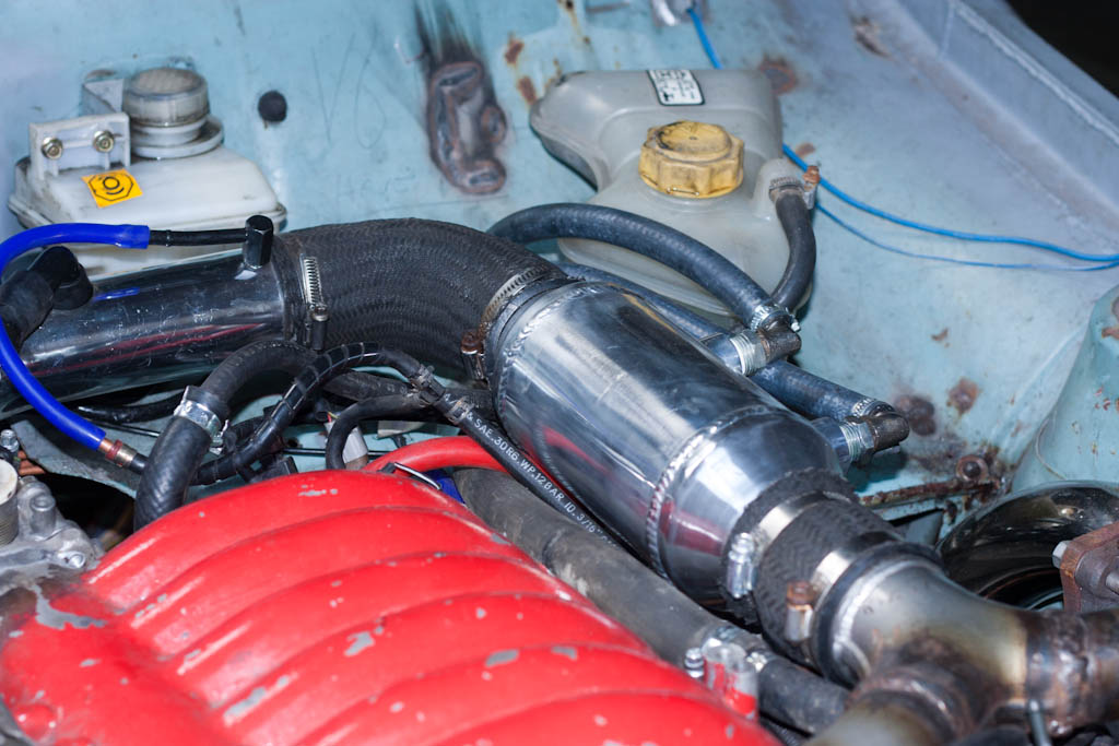
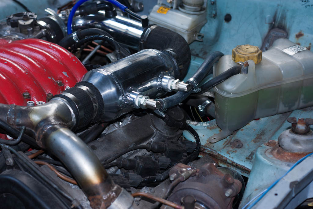
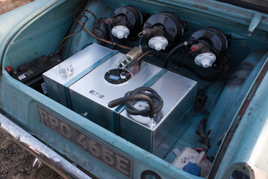
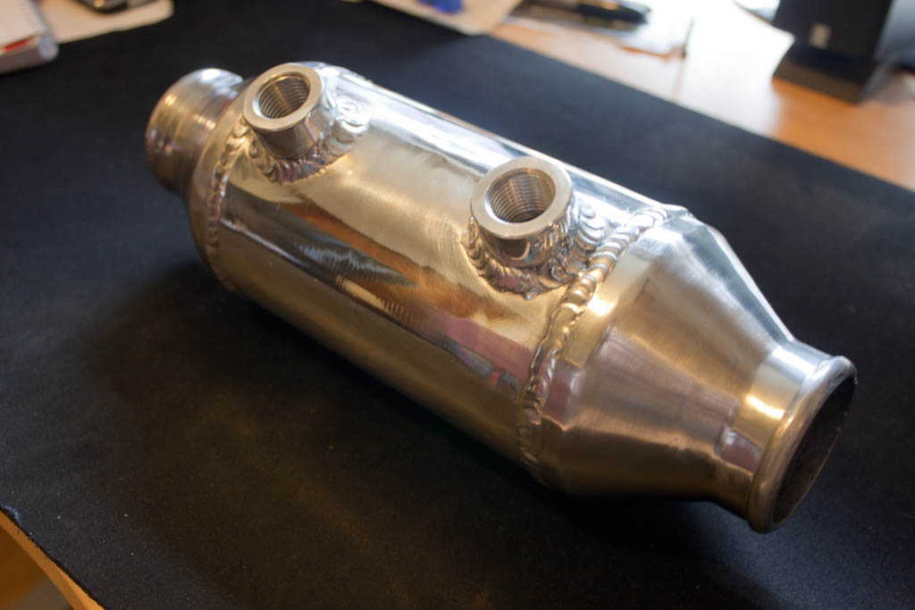
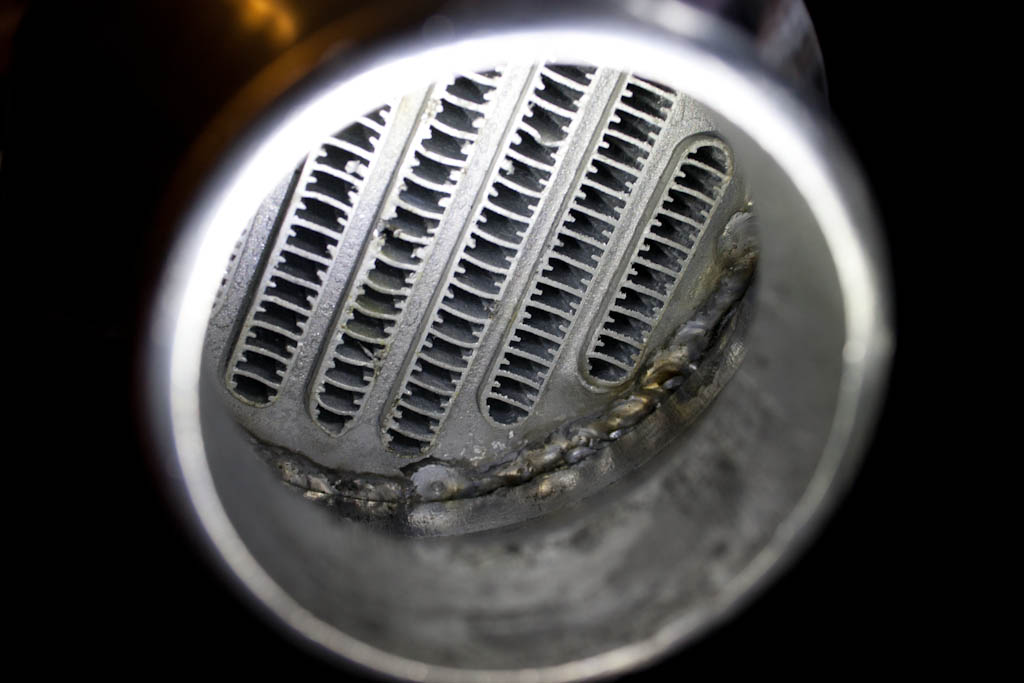
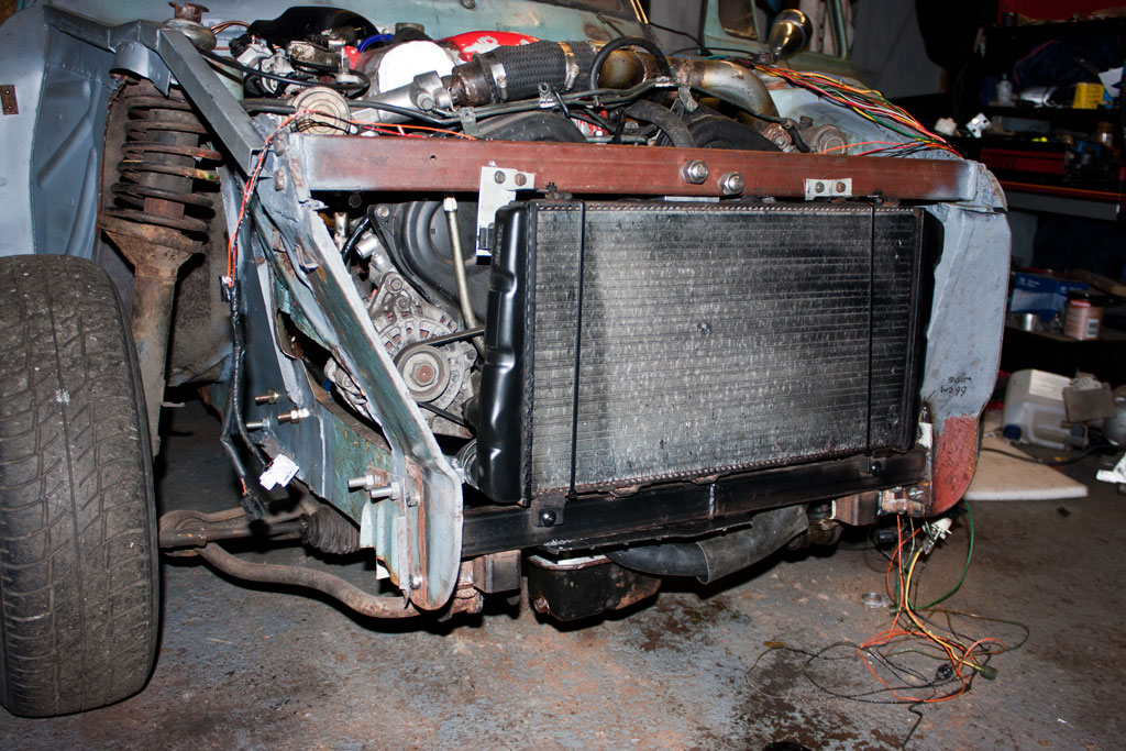
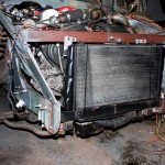
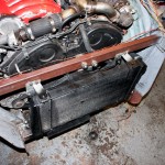
With it starting and running nicely now, we decided to revisit the cooling system – the Mini radiator was always only a temporary solution until we had found something more suitable, which I now have.

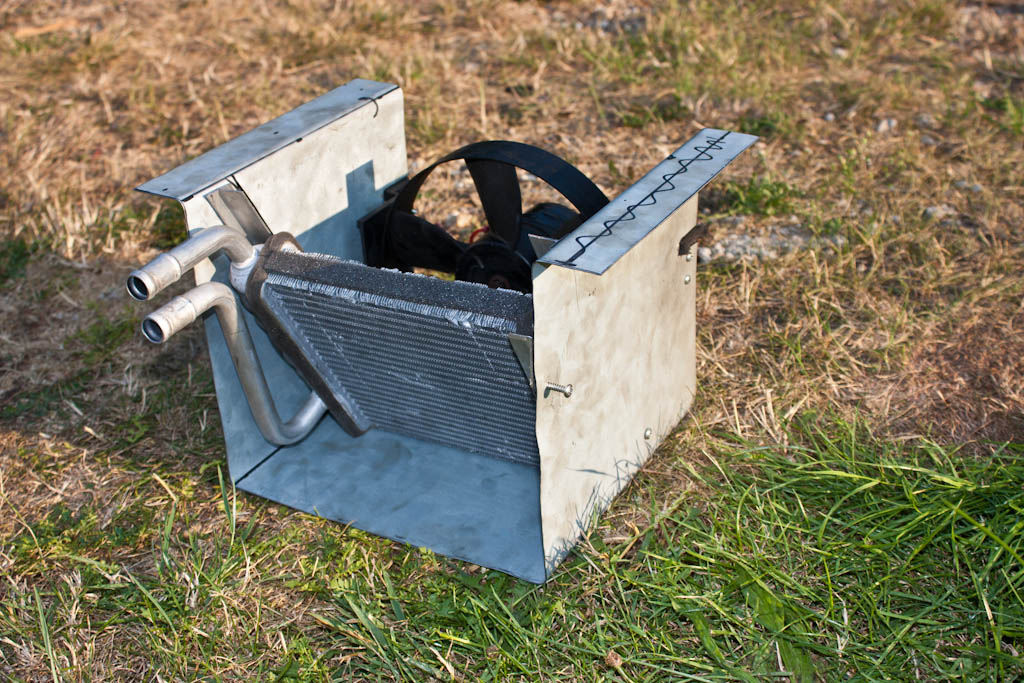
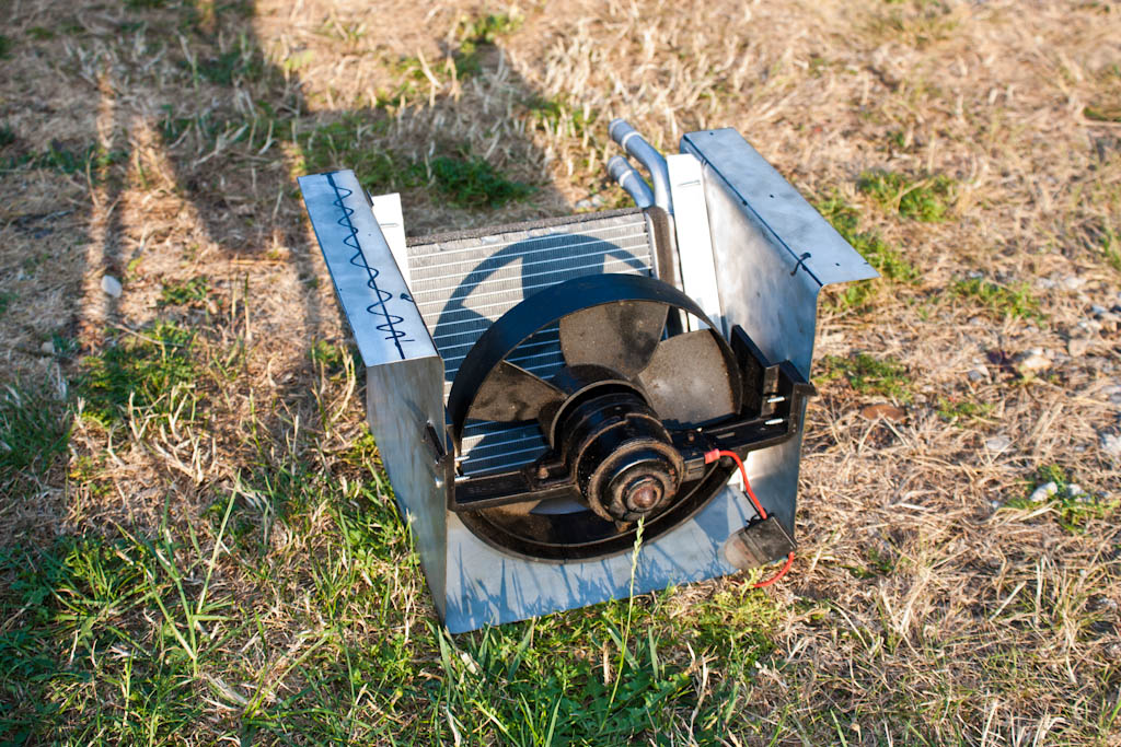
After removing the temporary radiator and fan, I attached a more suitable fan to the car, as well as mounting a radiator that will fit in the space available – this is from a Skoda Felicia – and is within 1cm of the dimensions we scribbled on the bulkhead a few months ago. It will be replaced with a new radiator in time – whether it’s a replacement OEM one to the same spec, or whether it’s a higher performance custom-made job – well, I’ll see how it fares with this standard one whenever it’s on the road.
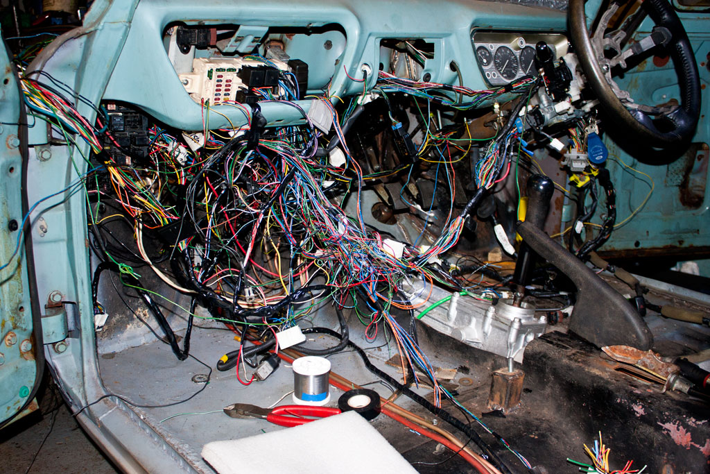
Cooling fan fitted Radiator - from a Skoda Felicia Radiator fitted

I HATE WIRING.

There, I said it. There’s so much excess wiring from the VR4 that I’m not needing in this car, and because everything’s in different places, and the car is smaller, there’s lots of wiring to do. It’s a daunting process, and it’s not often I feel like doing it.

However, it needs doing, so I decided to tackle it.

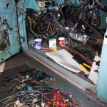
I started off by trying to undo the spaghetti tin of wiring that I had draped over the passenger footwell, to try to make some kind of sense of it.

This was a process that took a good couple of hours, just taping together wires that run parallel for more than 6 inches to see what goes where. And when I was done with that, I’d not removed any wiring, it wasn’t the final product, but it at least gave us a chance of seeing what goes where and what subsequently doesn’t need to be there.

Then came the task of tracing a wire, cutting it, re-routing it, and joining it back together. Repeat this hundreds of times for a different coloured wire, over and over, for hours on end, with only a few brief breaks for a cup of coffee and a biscuit…

Excess wiring removed Still some more wiring to tidy

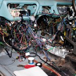
It still looks a bit of a mess, but wiring is a task where you need to do 95% of it before it looks like you’ve actually done anything with it.

On the plus side, the passenger floorpan is now mostly clear of wires, there are a number of bits which are properly loomed up and neat, and there’s a large pile of wires and connectors which have been removed, the only real evidence of actually having done anything…

Propped up and shafted

Having worked out the rough ride height with our temporary bracketry and solid bar, I ordered some adjustable shocks and springs, and we re-did the lower mount, and reinforced the top mount. The lower mount will have some additional bracing and welding completed the next time the axle is removed from the car and we can get to it all more easily.

Upper spring mount Lower spring mount Spring

With the de-dion now moving up and down like it should, we need to get some drive to the wheels.

The Nissan diff is about 50mm longer than the Anglia diff, so the Nissan propshaft, which bolted straight up to the Anglia diff, is now 50mm too long to bolt up to the Nissan diff.

Being a two piece propshaft, we pulled the rear part off, and set about removing 50mm from the length. By clamping it in the vice and utilising a spirit level, we were able to get a clean cut to reposition as necessary.

Propshaft preparation Propshaft preparation

With the propshaft cut to length, next to tackle is the driveshafts. The Anglia is a lot narrower than the Nissan, so a touch more than 50mm needs to be removed from the overall width.

We cut the driveshaft down, and with the use of a lathe and an angle grinder, we V’d the ends to provide a large surface area to weld the two ends back together.

Driveshaft preparation

Once welded together, the driveshafts were checked for straightness on the lathe, and the boots were refitted, albeit much closer than previously, and the new driveshafts are attached to the car.

Nearside driveshaft Offside driveshaft

The propshaft and driveshaft modifications done here may not be the final parts used on the car. What they will do, however, is allow me to put something together, which will be at least enough to move the vehicle under its own power, and prove the concept. They may stay on the car, they may fail spectacularly the first time any serious power is applied to them – if they work, brilliant, if they don’t, all I’ve lost is a couple of hours of time, and I’ll get some made up elsewhere.

A couple of shots of the diff mountings now. These are rubber bushes within a length of tube, with a long bolt going through into the body. Should absorb some of the vibrations/noise coming from the diff…

Rear diff mount Front diff mount Front diff mount

And finally, the completed article. One completely home-made, custom rear axle, to my exact specifications, and should be strong enough to take whatever power the engine can throw at it.

Completed rear axle

We then couldn’t resist driving it outside for its first little photoshoot outside of the confines of the garage, and to enjoy the surprisingly good weather.

IMG_4824 IMG_4826 IMG_4829

Rear axle: Part 2

Next up on the axle, is the trailing arms. There will be 2 trailing arms on each side, which will prevent the axle from twisting under braking or acceleration.

First up, is to fabricate the mounts on the axle. Utilising some heavy box section, a mount is added to the top and bottom on each side, and fitted with heavy duty M14 rose joints.

IMG_4444 IMG_4440 IMG_4443 IMG_4441 IMG_4442

With the axle end done and offered up to the car, the body end of the trailing arms take shape. The original rotten spring hangers are removed, and another bit of heavy box section is tacked into place, as well as the trailing arms fabricated at the correct length. The trailing arms are made equal in length, and have one left-handed and one right-handed thread rose joint attached – this will allow infinitely fine adjustment to the positioning of the axle within the wheel arch without having to remove it from the car.

IMG_4450 IMG_4451

Additional bracing begins being added to the mounts and the floor/box section. There is still more to be finished.

IMG_4452 IMG_4453 IMG_4760

In order to set the ride height and calculate length of shocks/springs needed, a temporary solution is tacked into place – a length of box section and couple of temporary brackets.

IMG_4758 IMG_4761

The trailing arms will prevent the axle from moving forwards/backwards, but will not prevent it from moving left/right. To prevent this movement, a panhard bar is added. This attaches to the axle on one side, and to the body on the other.

A heavy duty bracket is fabricated and attached to the floor – this wraps around the chassis rail for additional strength.

IMG_4763

The panhard, like the trailing arms, is fitted with a left-hand and a right-hand threaded heavy duty rose joint, which will allow fine adjustment of the left/right position of the axle without removing anything from the car.

IMG_4767 IMG_4769

The diff was also lifted back into the rough location, a length of angle has been added to the mount to move the load closer to the edge of the boot floor, closer to the chassis rails where there is more strength.

Finally – a wheel with tyre (currently 185/60/13) is fitted to see what it would look like.

IMG_4756

Classic Ford

I’ve just had something drop through my door…

Classic Ford - June 2013

A couple of months ago, I had a couple of guys from Classic Ford come and visit for the day, and they’ve written up an article for the Grafters section in Classic Ford.

So – grab yourself a copy of the June 2013 edition of Classic Ford and check out page 8.

Rear axle

Work this time continues on from the work done in the last update – namely the fabrication of a completely custom rear axle.

Having marked out and cut out the bits to mount the bearing units and calipers for the near side, we moved onto doing the same for the offside. After getting everything lined up and fitted to the wheels, it came apart, the paint removed from all bits, and the two parts previously seen were welded together.

After that, the hub bucket (#6) was measure, cut and welded, and it was all reassembled and affixed back to the wheels.

We had also added more to the diff mount, a large piece of heavy-gauge angle section, which will help to spread the load from the diff across a larger section of the body – this is wide enough to be almost touching the chassis rails on either side.

Rear axle Rear axle

We then measured and cut for the main de-dion tube, and began to tack together. We had to be very careful here to get the alignment spot on – any toe-in or toe-out and it will scrub tyres.

Rear axle Rear axle

There is still additional bracing to affix between the de-dion tube and the hub buckets, which will also perform the task of trailing arm mounts.

Rear axle and suspension – the beginning

This may cause some heated discussion on some forums – the topic of rear axle and suspension.

Some will argue that the standard rear axle will be good enough for more power. My dad’s experience says otherwise – in the early 70’s he was breaking diffs with just a 1500GT engine and some aggressive starts – but those were the days when Anglias were easily found in scrap yards, and a diff could be broken on a Friday night, and a replacement sourced and fitted by lunchtime on Saturday.

However, this is 2013, and parts for a Ford Anglia aren’t as easy to come by now.

Therefore – I have decided that I do not want to use any parts of the original rear axle.

I am absolutely not putting wider arches on it, so a wider axle is also out of the question, which means something custom made.

I have a perfectly good diff from the 200SX, which I know will take the ~300ft-lb of torque from the engine, as well as the rear hub units, so instead, I shall be making my own rear axle.

This will allow me to have it the exact width I need, using a diff that I know is good.

I had a long debate with my dad regarding what to do about rear suspension (since, in fact, when I purchased the 200SX), and we debated the original axle (not strong enough), and making either 1) a new live axle, 2) a de-dion tube or 3) fully independent

After discussion of the advantages and disadvantages of each, we decided on a de-dion tube setup. The wheels are linked together, much like a live axle, but instead of the diff being part of this, it is mounted to the floor, with a pair of driveshafts with CV joints to allow travel in the suspension. This will then have a 5-link setup to allow movement and location, with a pair of trailing arms on either side, and a panhard rod to prevent sideways travel of the axle.

rorty-de-dion-design

The above is a design by Rorty Designs, published a number of years back for the LocostBuilders site, based around Sierra parts to replace an Escort live axle on a Lotus-7 style kit car, and has been made by kit-car owners a number of times.

I will not be using Sierra bits (as I don’t have any), so instead will be using this as a general idea of what to do based around the 200SX bits that I do have.

To begin, we set up a board with the wheels and diff, setting the wheels parallel and at the desired width to allow the wheels & tyres to sit within the confines of the standard wheelarches.

Jig for rear suspension Jig for rear suspension

We then began to align the differential to the car, aligning it centrally (to give us equal length driveshafts) – which does mean that the nose will be slightly offset, but the propshaft has enough movement to allow this slight offset.

Diff alignment Diff alignment Diff alignment Diff alignment

With the diff alignment mostly sorted, it was then time to look at the de-dion part of the suspension.

In order to attach the hubs, we need to make up some plates to affix this tube to the bearings. Firstly, was to strip down the 200SX rear hubs, and leave ourselves with the wheel bearing and brake disc assembly. The 265mm discs fit nicely under the 13″ Ford wheels.

200SX rear wheel bearing and disc

We then start with a template, which will be the first piece of the puzzle. This will bolt to the wheel bearing, and will have the de-dion tube attached to (#2 in the above plans).

De-Dion #1 De-Dion #2 De-Dion #3

When this was cleaned up, it was attached to the bearing unit.

De-Dion #4

Caliper mounts (#3 in the above plans) were then made to take the 200SX brakes, putting them in the correct position, giving plenty of clearance within the wheels.

De-Dion #5 De-Dion #6

Next is to make the hub bucket (#6 in the above plans), attach the main de-dion tube (#1), and make up the trailing arm brackets (#7), trailing arms, panhard rod (#12) and the other little brackets to affix.