MAF, MAP?

In ye old days, the amount of air/fuel in the engine was determined by the carburettor.

Modern cars measure how much air is coming into the engine in a number of ways, and the Engine Control Unit uses this value to determine how long to open the Injector to add the right amount of fuel.

The two ways of measuring how much air is going into the engine is by using a Mass Airflow Sensor (MAF) or Manifold Absolute Pressure (MAP).

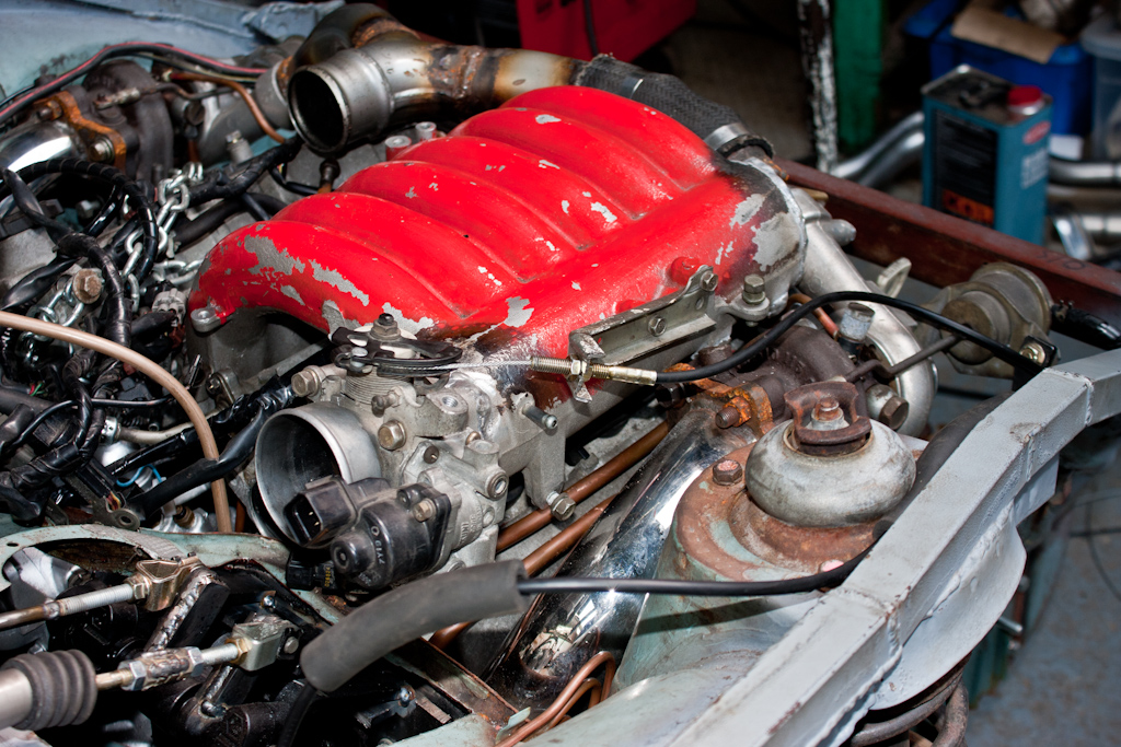
The Mass Airflow Sensor originally used on the Mitsubishi Galant that the engine came from uses the phenomenon of a Kármán Vortex Street – the principle that air flowing around a blunt object comes back together in “pulses” to create vortices – the faster the air is flowing, the more vortices are created in a given time interval. (Other vehicles use different types of MAF, which measure the air in different ways)

This is where we get to the second method for detecting how much air is in the engine – Manifold Absolute Pressure (MAP)

This method uses a pressure sensor in the manifold, and the engine speed to calculate how much air is in the engine.

Each of these methods also make use of an Intake Air Temperature sensor (air is more dense when it’s cold), and a barometric pressure sensor (air is thinner as you go higher) to calculate the amount of air more accurately.

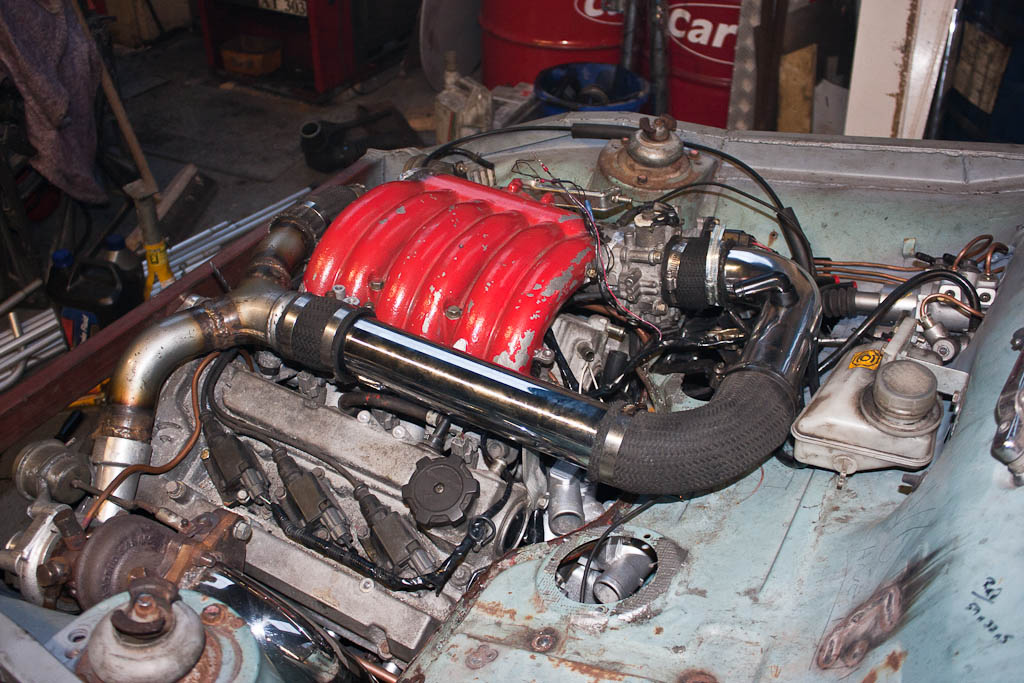
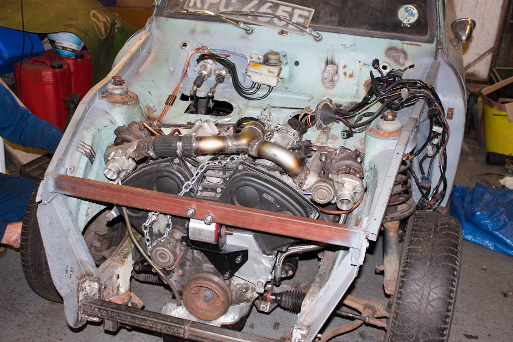
On the original Galant, the MAF is placed very early in the inlet – immediately after the filter, and before the turbos. Given the space constraints of the Anglia compared to the Galant – there is not enough room to locate the filter and MAF and get the air pipework to each of the turbo inlets.

Therefore, some clever soul in New Zealand invented the MAP-ECU. This little magic box of tricks makes use of a MAP sensor and engine RPM, and will emulate the frequency output of the original MAF, so that the standard ECU is still getting the signal it expects.

It can either be programmed from scratch with the correct values, or it can be run in “auto-learn” mode, where you will run the vehicle for a while with the original MAF still connected, and the MAP-ECU will learn what the standard MAF is outputting for the various pressure/RPM cells.

The problem I had with the engine not revving was that the MAP-ECU was not correctly configured for how I had wired it up. The original owner of the MAP-ECU had the RPM signal connected to the wire which had the pulses from all 6 spark plugs (so to get the correct RPM, you divide the number of pulses received by 6) – I had wired it to the signal for just 2 spark plugs – so as the engine revs increased, the MAP-ECU was not moving into the correct cell, and was not telling the standard ECU that there was more air going into the engine. Once I told the MAP-ECU to divide the number of pulses it’s seeing by 2, it was reading the correct RPM.

Cooling down

After managing to get the engine up and running last time, we had a small issue – any touch of the throttle would cause the engine to stall.

We didn’t run the engine much past what was shown in the previous video, as we had no way to cool the engine. So, we spent some time putting together a cooling system, which would allow us to run the engine for longer than a couple of minutes, and perform some troubleshooting.

With some pipework made from some large bore pipe, and a loop of pipe on the heater circuit, we hooked up an old Mini radiator we had sitting around, to be able to get some coolant into it.

We refilled the “petrol tank” with petrol, hooked up the battery again, and I hooked up my laptop to the engine ECU to run EvoScan, and to the MAP-ECU to run the MAP-CAL software.

Upon starting the car, we could see that the RPM within EvoScan was around 700rpm, but it was showing at just 200rpm in MAP-CAL. The MAP-ECU was previously attached to a 6A13TT engine, and in the configuration it had been set to “6 cylinder”. The RPM wiring had obviously been on the signal to the tacho in the dash, rather than how we’ve now wired it – direct into the signal from the ECU to one of the coils. Changing the MAP-ECU configuration to “2 cylinder” then showed the correct RPM – and instantly we were able to rev the car properly.

The MAP-ECU “mimicks” the Kármán Vortex Frequency given out by the standard MAF by utilising RPM, manifold absolute pressure and intake air temperature – with the RPM incorrectly set, it wasn’t moving out of the correct RPM/pressure cell and adjusting the VKF frequency output correctly – this was then not telling the standard ECU that the amount of air had changed (increased), so was not adjusting the fuelling correctly – hence the immediate stalling.

Down to the wiring

In my excitement to post up the video last time, I didn’t get round to adding some additional photos that were taken. So… here they are!

I start this update again with another photo of the engine and gearbox out of the car – this time to finish welding up the exhause downpipes where we couldn’t get to them whilst it was in the car. We also took the opportunity to begin tidying up and re-routing some of the cabling from the engine, as our work last year to route it all through the existing heater hole was beginning to look a little too untidy for my liking.

The engine and gearbox went back into the car, and we put the remaining engine wiring back on, and continued to re-route and tidy, and in the process put all of the engine wiring into waterproof plugs, so that it’s easy to disconnect from the rest of the car.

Once that was done, the engine bay is looking a lot neater without all that wiring on show.

Then onto the daunting task… sorting out the rest of the wiring. We had already removed quite a lot of unneeded wiring last year by removing everything attached to the automatic gearbox ECU, but it still left a large amount, so it was time to try to plug it all together, and work out what went where in the original Galant, so we can begin cutting unneeded bits out.


Now… what goes where again?

Once everything had been laid out and identified, we began to cut out the unneeded bits – AYC wiring, Active Stability Control wiring, ABS wiring, rear doors, heated rear screen, stereo wiring… To do this, we removed all the existing spiral wrap and insulation tape, and began at the endpoints of these systems, separating the wiring into “wanted” and “not wanted”. The “not wanted” bits were chopped out when we reached a connector plug, and then chased from the other side of the plug and removed.

There’s probably still more to come out, but we’d identified a large amount to remove, and we were confident that what we had was sufficient to get to the final end goal of the weekend – which was to start the car! You’ve seen the results of that already!

On a visit to the scrap yard, we spied a nice bit of aluminium pipe which looked like it might have been perfect for the inlet tract – so we quickly knocked together the remainder of the inlet. The straight bit off the Y-piece will be replaced with a water-to-air charge-cooler.

So… what was does the un-needed wiring look like…?

That doesn’t even include any of the automatic transmission etc stuff we removed last year!

And finally… the final bit of original Anglia wiring to be removed, the front-rear loom:

Completely Exhausted

The timing of this update is quite apt, having just received an email from Old Skool Ford forum listing their Favourite Projects, and included in the list is my little project! So, a huge thanks to the staff at OSF for the shout in their mass email!

It starts with a quick trip to collect some shiny bits for a good price, and to try to squeeze it into the back of a Fiesta because I forgot to pick up the hacksaw I placed in the hallway the previous night before leaving – which in itself was quite a feat of engineering! 😉

Having successfully collected the exhaust, which was previously fitted to a VR-4, the backboxes were chopped from the pipework, and lifted into place to measure up and see what it would look like with the 5″ exit… the answer… a little stupid, especially on such a small car! No pic, unfortunately!

So, the outlets were also chopped off, and the boxes were lifted into place to measure up for the other pipework.

The exhaust bits already on the car were marked, cut, and adjusted to follow the line of the floor better, and in preperation for adding of the next parts.

I also purchased some 2.5″ stainless over-axle exhaust sections, as they were available cheaper than making our own sections or buying various angled bits and welding together ourselves. These were fitted to the backboxes, and some brackets were made and welded to the chassis to support via some new exhaust rubbers.

Moving onto tailpipes, and we again utilised some offcuts from a section that has provided other parts of the exhaust, which was the enclosed ends of the bumper bar which forms the turbo elbows. The rear valance was roughly chopped to accomodate the second tailpipe, and they were fitted.

The enclosed bits were removed to give a pair of downdraught tailpipes – and hopefully nicely subtle!

Some assistance required

After a small break to do some running repairs to the garage building, I’m back with another update.

The first job was to unbox and mount the servos that were purchased last time – the only place for them is in the boot. Some minor modifications to the supplied mounting brackets, and they’re all lined up at the front of the boot.

With 3 servos so far from the engine, and needing to be operated by vacuum, the usual route of providing vacuum from the inlet manifold on the engine would not have been ideal – especially with a turbo engine and requiring a servo for the clutch, enough vacuum can not be guaranteed. Therefore, we have decided to make use of an old CO2 welding bottle as a vacuum chamber to provide a large amount of vacuum to the 3 servos.

The bottle was fitted with some barbs to fit pipework to, and fitted into the boot of the car, and a mounting bracket was fabricated to support the end of the bottle where it tapers.

As I mentioned earlier, the vaccum will not be provided by the engine, so instead outside assistance is required to provide a vacuum. There are many vacuum pumps available, but most of these are driven directly from the engine, and the majority of these also require an oil supply – something that’s not going to be easy. Therefore, we found an electric vaccum pump, usually fitted to various VAG cars (this one listed as being for an Audi TT), which requires purely a 12v electrical connection. A vibration-reducing mount was made using an old cotton-reel style rubber mount, and it was plumbed up to the vacuum chamber.

Applying 12v power to the vacuum pump until the chamber was “full” (or should that be empty?) of vacuum – it was time to test the clutch out. As predicted, this greatly reduced the effort required to operate the clutch, but it still it was not enough to make it comfortable to use – I want this to be a car that’s not a chore to drive, and to have a modern feel to it. Therefore, to aid the servo assistance, we also adjusted the pedals slightly to further improve the levering force available from the pedal to reduce effort. The arms that operate the master cylinders was shortened, and the operating arms inside were lengthened slightly.

The combination of adjustments to the pedals, and the servos, has made the clutch operation now akin to a modern car – and I currently also only have a standard FTO clutch cover fitted – which may need to be uprated to one with higher clamping force to cope with putting down the 50% extra power over and above what a standard FTO clutch is designed for – this will add more resistance to the clutch system – and the assistance of the servo is definitely still required.

Now that the clutch and brake pedals were sorted, why not finish off the trio, with a new throttle cable hooked up, and a custom bracket made to attach it to the inlet manifold at the required angle to match with the adjusted throttle body location.

Flexible working hours

A bit more exhaustive work for this update. The next thing on the list was to continue with the exhaust. After getting down to the underneath of the car last time, we chopped off the excess, and welded on some flanges, and added a flexi section to allow engine movement, one with the mounting for an oxygen sensor, and a pair of nice straight bits of stainless pipe (Isuzu Trooper side step bars).

Also, whilst we were underneath the car, we’ve run two brake pipes from the master cylinder to the boot, where the brakes will be assisted by a pair of 1.9:1 remote brake servos. We also ran the fuel feed and return pipes from the engine bay to the boot, where we will put a petrol tank.

To finish off, another braided hose from Hosequip for the clutch, a couple of inches longer than the standard 200SX hose, and we were able to test out the clutch for the first time.

Unfortunately, a little hitch – the clutch is VERY heavy to use. However, whilst wandering around the Bromley Pageant of Motoring yesterday (where we went with my dad’s 4 wheel drive Anglia) we found a 3:1 ratio remote brake servo, which should reduce the effort required to operate the clutch.

So, looks like it’ll need yet another pipe running to the boot and back down the length of the car!

An exhausting time

By moving the turbos from their natural home, the original oil and water feed & return pipes were no longer suitable. The water pipes have already been done, but the oil pipes required a bit of external help to ensure we had pipework suitable for the temperature and pressure of the oil. We contacted Hosequip who are based not far down the road, and talked to John who has made up some wonderful braided hoses.

With these in place, and the oil feed coming from the back of the block, we reassembled the rest of the engine and gearbox, and checked the fit of the starter motor with the new gearbox.

Before fitting this back into the car, we started to run the brake and clutch lines down the corner of the engine bay – access is a little tricky with the engine in place!

The new oil lines look great through the front.

We’d identified that the original gearbox mount we made was not quite correctly aligned, and was putting some twist into the mount – but it was done before the engine & gearbox were properly mounted, so it’s not too surprising that it needed a small tweak. Once this was done, and the rubber mount sitting correctly, we attached the clutch slave cylinder to the side of the gearbox.

Taking some more of the stainless bumper bars, we continued working on the exhaust.

Using two corner pieces, and the centre section of the bit used for the bits directly off the turbos, we brought the pipes towards the gearbox, away from the steering column, and turned towards the back of the car.

From the side it looks a little low, but none of it is any lower than the front crossmember, which is the lowest point of the car – there’s still plenty of ground clearance so speedbumps shouldn’t be an issue I hope!

A Little Squirt

With the engine & gearbox out and on the bench, it’s time to do some of the bits that are easiest done whilst the engine isn’t in the car.

When I removed the engine from the Galant, it was late one evening and I had limited tools, and I was unable to separate the gearbox and transfer box, or remove the torque converter! So, in the limited time I had, I decided the easiest thing was to remove the sump – so this needs to be sealed up properly again. Whilst the sump was off being cleaned, why not give it all a little squirt of paint to tidy it up a little?

The very bottom sump pan isn’t in great condition, so I’ll be looking for a replacement – hence why it’s not been painted yet!

Also gave the exhaust bits a lick of high temperature paint to cover the bare welds.

During storage, the original 200SX gearbox got slightly waterlogged, and it’s no longer particularly smooth. I managed to pick up another gearbox in good condition, doing a swap for the 200SX engine. This then needed modding as the original did to fit the starter motor and the water manifold to the engine. As it was originally modded in the car, the cuts weren’t the neatest, so with the new gearbox on the bench, the modifications were made again, neater, and with a closer fit. It then had a good clean down, and a squirt with some paint as well.

Whilst the paint was drying, another small patch on the chassis, this one to cover over the original holes for the pedals, and cleaned up and slightly enlarged the holes cut out for access to the coolant pipes in the bulkhead, and for ease of fitting the alternator in the inner wing. These holes will have small ridges welded around them for screw-in panels at a later date.

Engine and gearbox removal

We’ve come to a point where the engine and gearbox being in the car is preventing us from moving on.

There’s minor tweaks that need to take place to the inner wings with a large hammer, there’s more pipework for the turbos to be made, and stuff like brake/clutch lines to be made up, and all of this stuff will be much easier with the engine and gearbox not in the way.

We disconnected the wiring from the engine, dropped the front crossmember down to allow us room to move the engine, and decided to see whether we could remove both engine and gearbox as one complete unit.

We couldn’t.

There was not enough movement for the sump to clear the front chassis rail. We’d already decided long ago that we’d remove this and replace it with a bolt-in section, and now seemed the perfect opportunity to do so.

We made some measurements, and went about cutting this front rail out. It went with a small “ping” as the chassis, relieved of tension, sprung apart by about 5mm. Good job we’d measured first!

With the bulk removed, we continued lifting the engine and gearbox out.

(Excuse my dad’s “I’m looking quite smug” look! I was actually sporting one too, but seeing as I was behind the camera, not in front of it…)

With the engine out, we moved it onto the bench, and could see better the oil filter in place on the side of the block (usually on a VR-4 there is a 90 degree adapter and it’s lower down, facing upwards), the turbo coolant pipework, as well as the adapters to move the turbos to a more suitable location.

(Some blatant product placement again… but you can’t beat a nice Hobnob and a cup of coffee to keep your strength up!)

With the engine and gearbox safely on the bench, attention turned to putting the strength back into the chassis that we’d cut out earlier.

We began by removing the remaining parts of the original front panel.

Then made up and welded in place some new bits, along with studs for location and securing.

The new crossmember was made up with brackets on the ends.

And bolted into place.

This is bolted both from the front, and the sides, and will pull the chassis rails back together to the same measurements they were before removing the original front panel.

Next, we added some mounts for the anti-roll bar.

The left-over time today was used to do a little bit of welding to tidy up a previously added panel – the driver’s floor pan.

We also added an additional mounting bolt for the suspension crossmember, just behind where we’d added the support for the engine roll-stop mounts (not pictured, but just behind the support to the left of the above photo)