In episode 12 of Garry’s Garage, I get my Wilwood pedals installed and mounted nice and securely.
I apologise for the poor audio quality in parts of the video.
In episode 12 of Garry’s Garage, I get my Wilwood pedals installed and mounted nice and securely.
I apologise for the poor audio quality in parts of the video.
Episode 11 of Garry’s Garage is live! I didn’t realise at the time that this was the start of quite a large rabbit hole I have led myself down!
Episode 10 is now live!
Soooo, it’s been a while since I last updated this site! How time has flown by!
I’ve done many a things to the car since then, but have been rather remiss in keeping track and documenting them!
I’ve now decided to do something I wish I’d done years ago when I started this project, and film it!
I’d really appreciate it if you could watch, like, share, subscribe etc! (Yeah, I know… everyone hates hearing this!)
Adjusting the handbrake helped with the noise and temperature, but the rear wheel bearings still needed replacing, so I stripped down the rear end to remove the bearings.
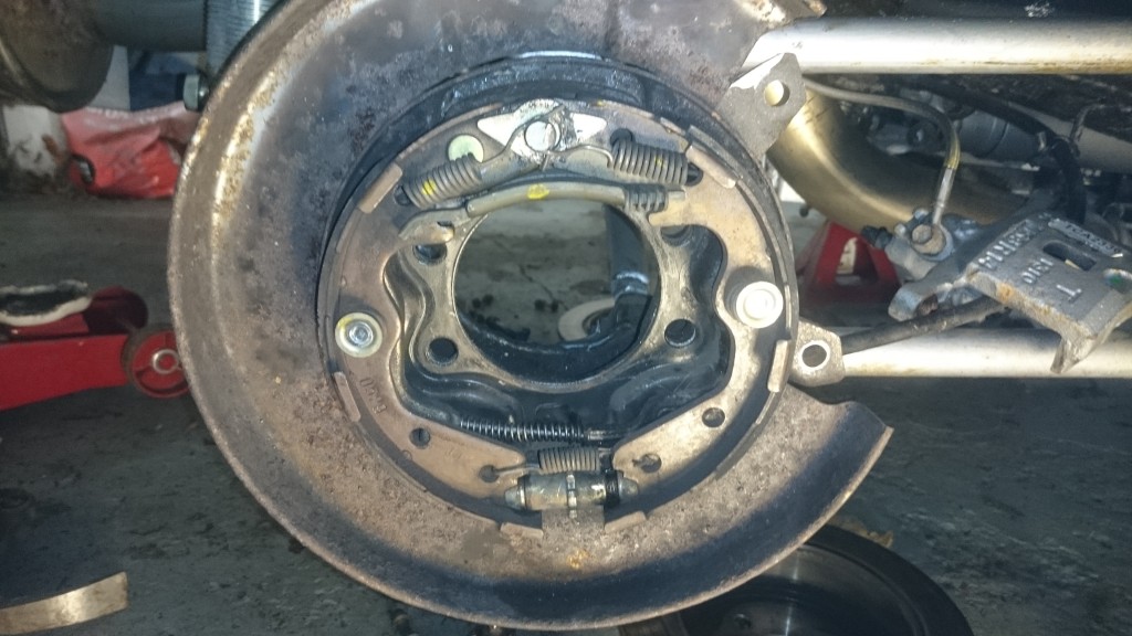
And then went a bit further…

I figured whilst I was there, I’d remove the rest of the brakes and tidy up the backing plates and calliper carriers.

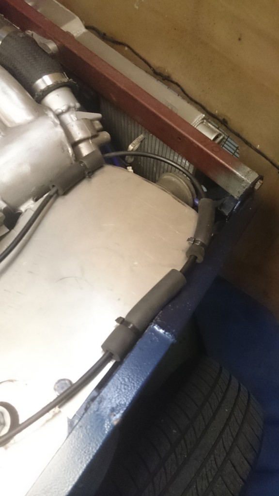
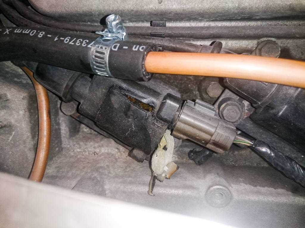
Continuing with the process of trying to eliminate noises, I found that the throttle cable was tapping against both the turbo heat shield and underneath of the bonnet. So a couple of extra cable ties will secure it better and stop it making a noise.
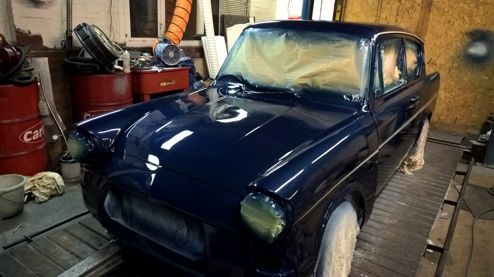
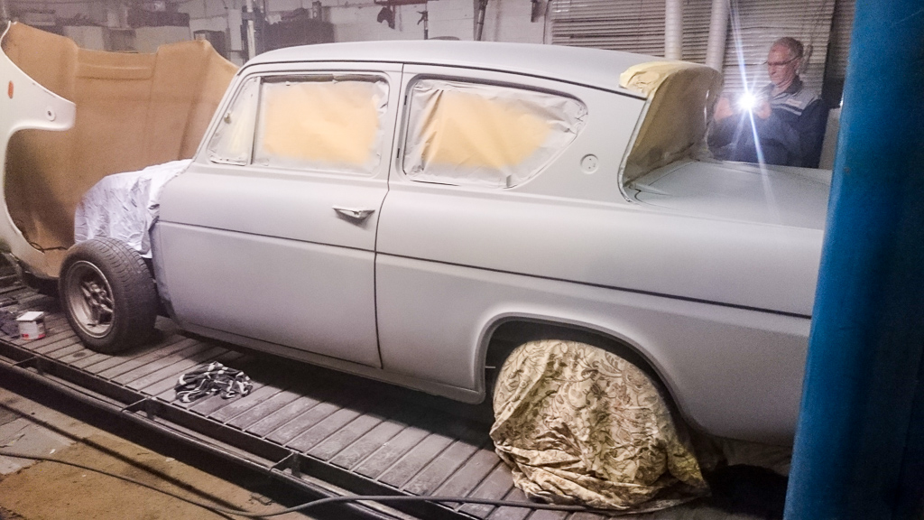
Since I fitted the new radiator, I didn’t like that it was visible from the front of the car. It was slightly too tall, but extra size is needed for the cooling capacity, so a section of the front panel beneath the number plate was removed. But, as the radiator was bright shiny aluminium, it stuck out like a sore thumb, and I was frustrated with it.
So I finally got round to disguising it with a squirt of black paint.

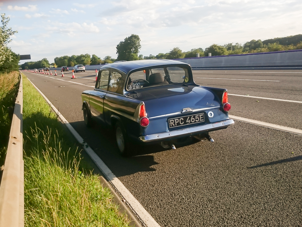
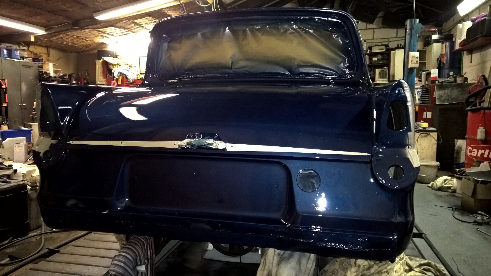
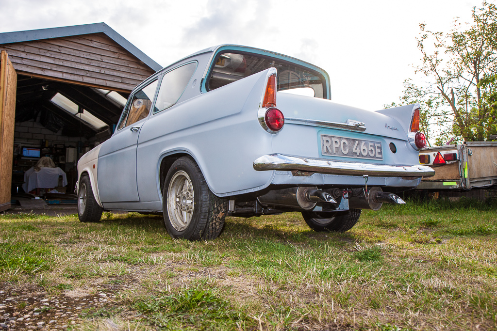
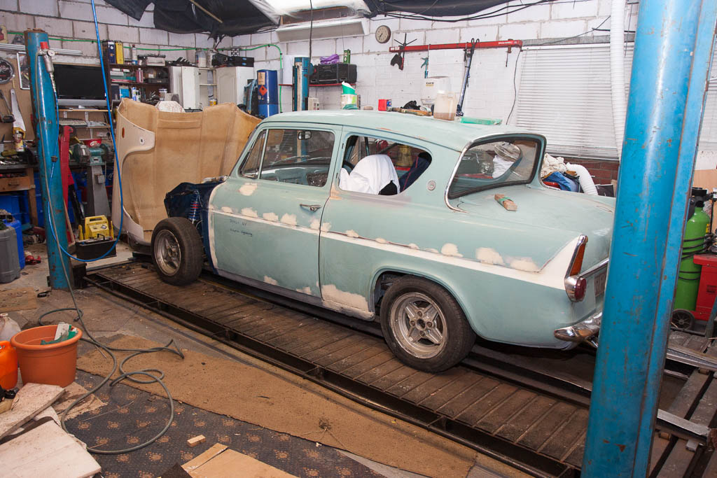
And, finally, there’s a nice shot from the front, so here’s one from the back too.

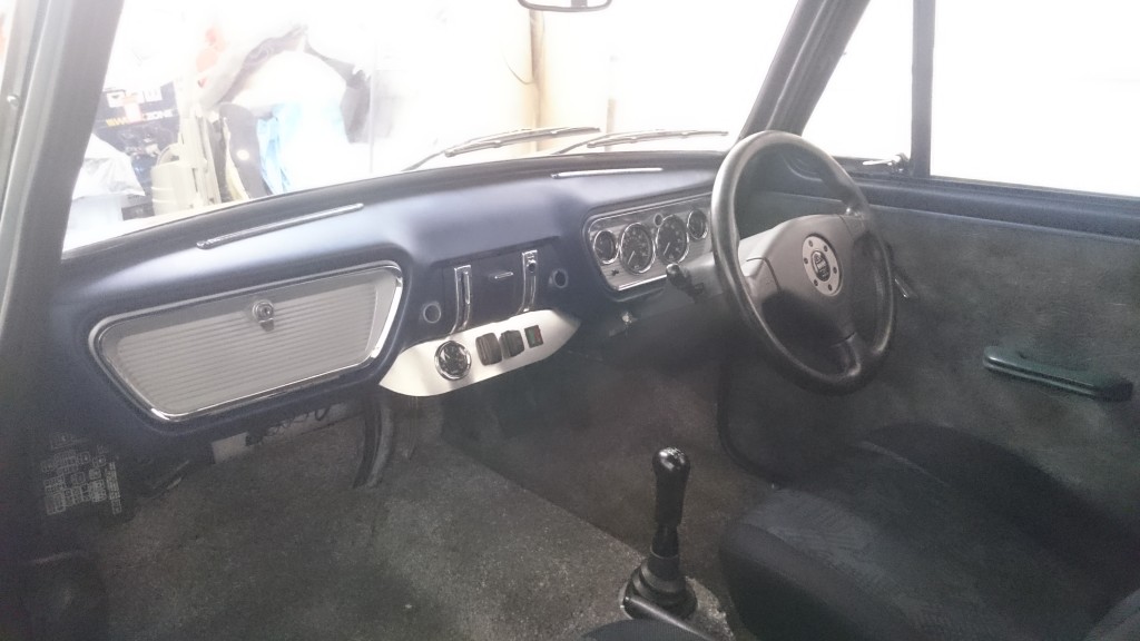
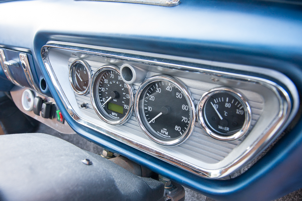
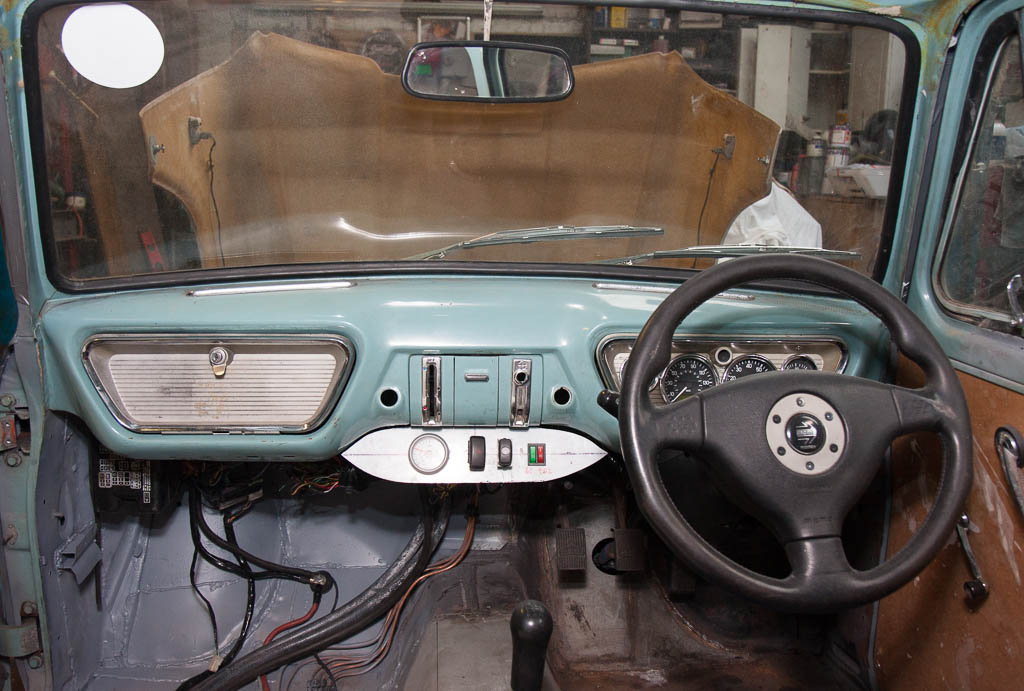
And last but not least, the interior as it currently stands, with the new ETB boost gauge.
2015 has been an exciting year – it marked the culmination of many years of work, finally getting the car out of the garage, onto the road, and subsequently back into the garage again!
After my last update in October (really, has it been that long!?), I did a little more tidying up of various parts.
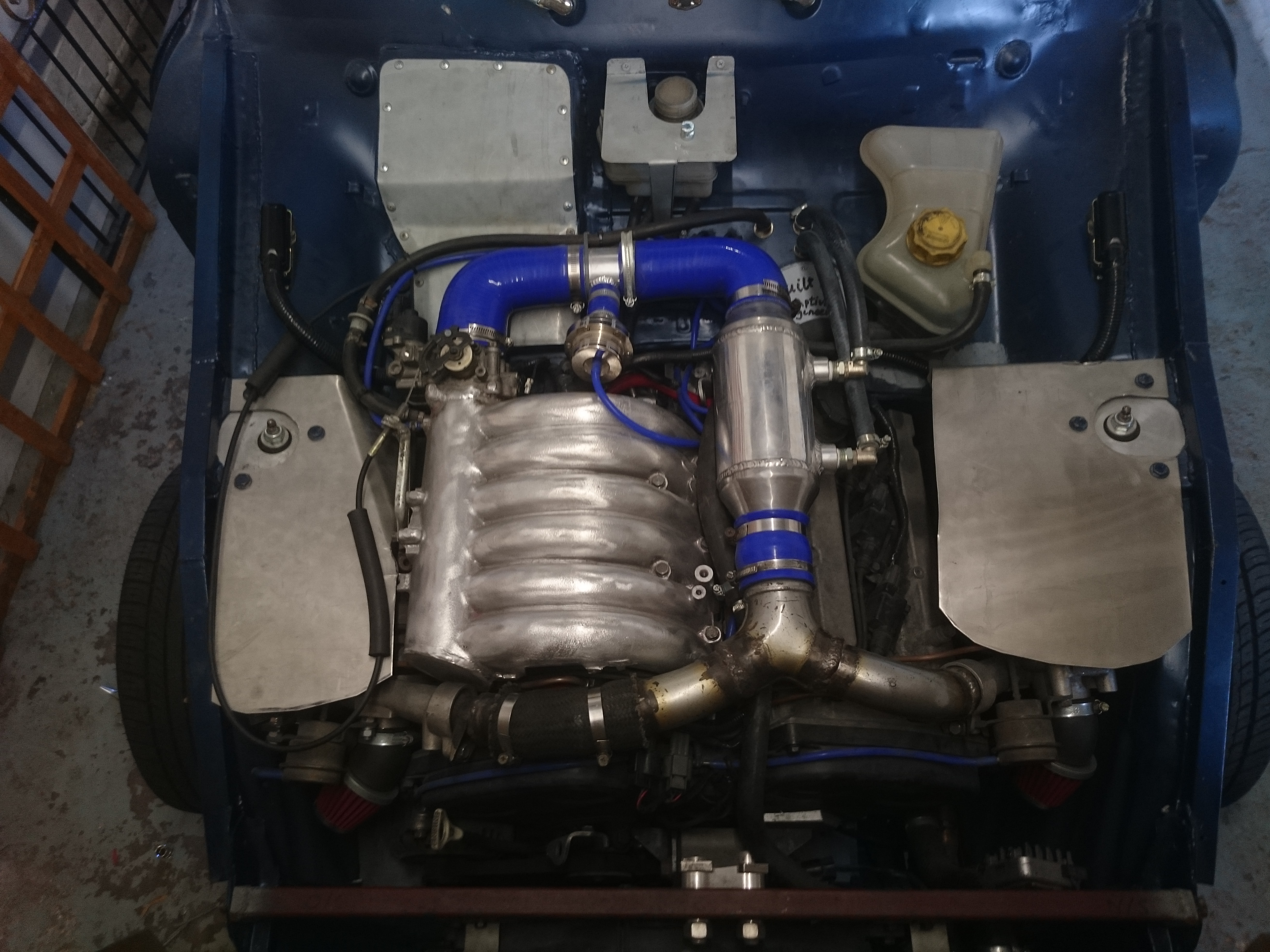
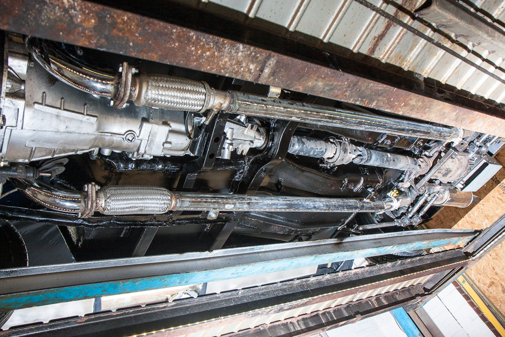
The brackets I painted for the engine were fitted back in place, as well as painting the post-turbo Y pipe, which really tidied up the look of the engine bay.

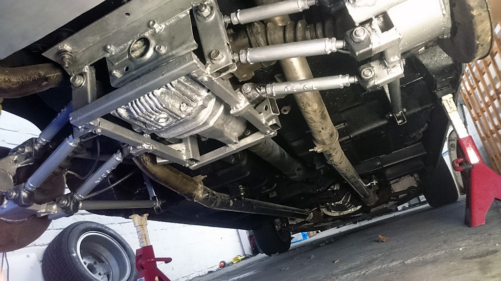
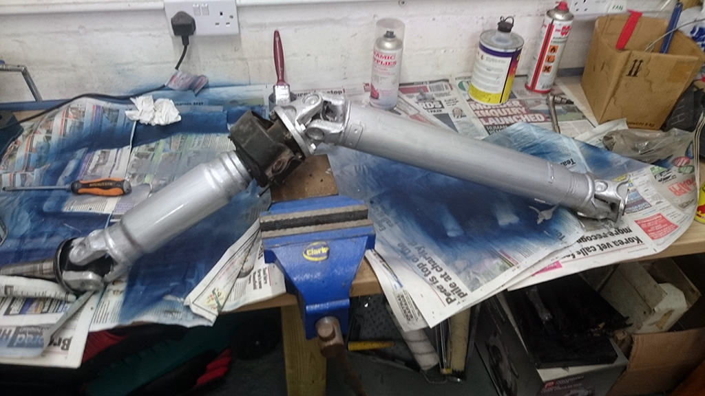
With painting on my mind, the next thing to tidy up was the rear suspension components, which were still in bare metal. I’d only driven it in the wet a couple of times, so before subjecting it to more moisture, time to give it a protective coat.
I decided on silver, as a contrast to the black underseal.
A common issue with the Nissan 200SX is that the centre propshaft bearing fails, and introduces noise to transmission. Whilst painting the suspension, I took the propshaft off to fit a new bearing.
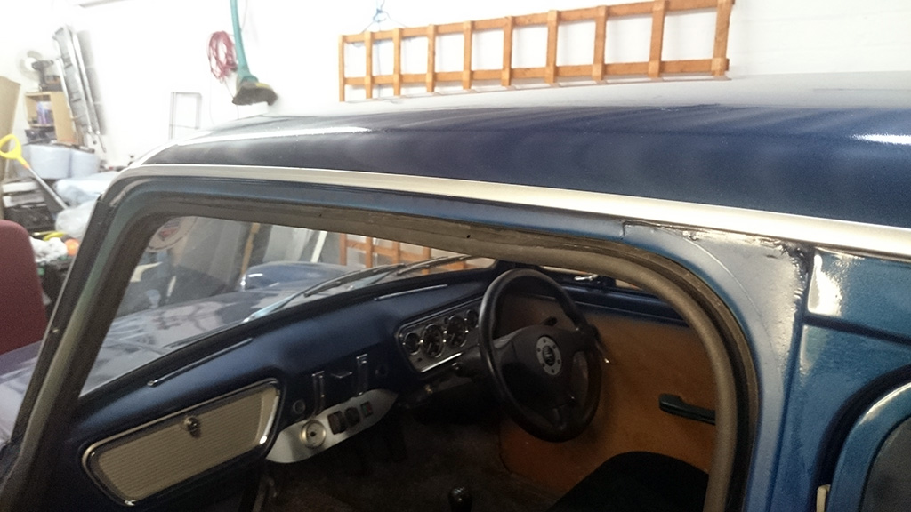
I’d been having a bit of (well, a lot of) wind noise and drafts coming past the doors. The doors still have the original rubbers on them, and until I do a full strip down for final paint and purchase fresh new rubbers from the Owners Club, I’ve fitted an additional rubber to the door opening on the body. This also covers the bare metal edge – two for the price of one! I found to my amazement that the one set of door rubbers I acquired for this (from a Vauxhall Zafira) are the exact perfect size to go around the door opening without any cutting or stretching!
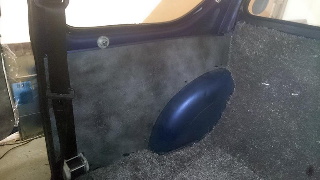
Next off I made up some interior side panels, and covered them with some grey material. I almost went for blue, but thought that the grey would make a nice contrast, and the blue might be too similar but different enough from the body colour to clash, rather than compliment!

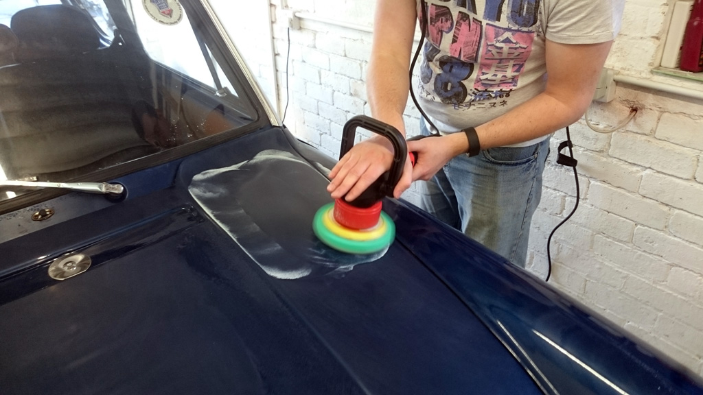
With the paint only ever being temporary, the finish wasn’t 100% perfect, and I never expected it to be. However, when a friend offered to go at it with his machine polisher, who am I to reject the offer!?
We first off gave the boot and bonnet a quick rub down with some 2000 grit sandpaper to get rid of the few surface imperfections, prior to going at it with the polisher.


With some smooth paint, it was time to head down to the NEC for the Classic Car Show, where I was invited to be on the Old Skool Ford stand.

On the way down, I stopped off to see a friend who can flash the Mitsubishi ECU, as I wanted a couple of tweaks applied.
My PLX wideband O2 sensor packed up, so it was not outputting the correct voltage to either the MAP-ECU for the wideband value (0-5v, which is only used for logging), or the simulated narrowband output (0-1v) to the ECU. With this outputting an incorrect voltage, the ECU was adjusting the fuelling to try to correct an incorrect air fuel ratio reading. With it disconnected, a Check Engine light was displayed.
So, I asked for the O2 sensor requirement to be removed, so that the ECU works purely from the fuel tables, and does not attempt to adjust the fuelling based on O2 sensor readings. This will slightly affect economy on a run, but I will not be fighting the adjustments when tuning.
Due to the work of a ClubVR4 forum member, the ECU can also be programmed to flash the Check Engine Light when Knock (pre-detonation) is detected. This gives a good indication to the driver (me) if there is something wrong with the fuelling or boost level that causes pre-detonation of the fuel in the cylinder.
With the computer hooked up, we did a couple of 3rd gear full throttle power runs to see what was what, including with a working wideband O2 sensor hooked up.
The Mitsubishi ECU calculates “load” based on RPM, throttle position, and airflow (amongst other things). On a typical Galant VR-4 doing a full throttle run, this Load value reaches around 240.
However, during our runs, this value only reached around 120!
The boost was also only reaching around 5psi, when it should be around 10psi, and the Wastegate Duty Cycle was at 100% trying to build up a higher Load value. The Wastegate solenoid is activated by the CPU in a “pulsed” mode to bleed off pressure from the wastegate to increase the overall boost pressure. This shouldn’t be at 100%, so it’s indicative of something not right!
The replacement prop bearing had made a positive difference to the noise level, but during the drive back from the NEC, there was still noise coming from the rear, and as I approached home, a new noise started. I stopped off to get some milk (having been gone for 4 days), and when I stopped I noticed that the hand brake wasn’t working as well as it should. Additionally, the passenger side rear wheel was warm to the touch, but the driver’s side was rather hot! I had suspected wheel bearings were needing a replacement (they had been sat outside with the 200SX rear subframe for a few years, exposed to the elements), so the car was tucked up in the garage, and not touched again until the new year!
First on the agenda for 2016 was to look into the handbrake and heat on the rear wheels. I stripped the rear hubs down to check the handbrake, and noticed that the cable had come away from the hook on the floor it should be hooked over. As I lifted the cable back into place, I noticed that the handbrake mechanism moved slightly within the driver’s side rear hub. This movement in the cable had been applying the handbrake slightly – causing the heat I felt. So, securing the cable to the hook, I slacked off the adjustment on the lever to give a mm or so of free play, and readjusted the handbrake mechanism on both rear wheels again.
Next was to look into the issues that may be causing it to be down on power. Firstly I looked at the boost solenoid, and found that it was stuck solid. Usually this switches on/off very quickly every second – the more it’s “on”, the higher the “Duty Cycle”, and the more air is bled away from the diaphragm trying to push the wastegate open to allow exhaust gas to bypass the turbine within the turbo. Bleeding all the air away (100% duty cycle) will cause the wastegate to stay shut. With the solenoid stuck closed, it was bleeding away none of the air, so the wategate was being pushed open at 5psi – the strength of the spring which pulls it closed.
I took the solenoid apart, freed it up and put it back together and tested it on the bench but it still didn’t work properly when in the car. One advantage of having a Legnum VR-4 as a daily car, is that I’ve got a full engine bay of spares! And, as luck would have it, the boost solenoid isn’t being used on the Legnum, as I have an aftermarket electronic boost controller, which has its own solenoid valve, leaving the standard one connected, but not in use. So, I was able to swap the two, and I now have around 10psi of boost – a reasonably healthy increase over 5psi!
I have also purchased a new wideband O2 controller, and a mechanical boost gauge from ETB Instruments to match my existing dials, which I have fitted, replacing the old.
And that’s pretty much up to date. There’s still more to do (isn’t there always!?)
I have, however, decided that I will be participating in a few (if not all) of the Old Skool Ford Drag Championship this year, which is being held at Santa Pod alongside a number of shows.
This will be a great opportunity to have some fun in the car, see what its performance is like, improve both the performance of the car and my drag racing skills, and provide a target for getting improvements and fixes implemented, and probably most importantly, meet some new people and have a laugh doing it!
So – I may see some of you at these events during the year! I’ll keep you informed here how I get on with the championship, as well as the trials and tribulations of it!
It’s been a while since I’ve had a chance to sit down and write an update, but here it is!
After a few more drives to get to know the car a bit better and taking it to some local meets, the first thing I did was to get a new radiator. This is much bigger, and thicker, and is bright and shiny and alloy.

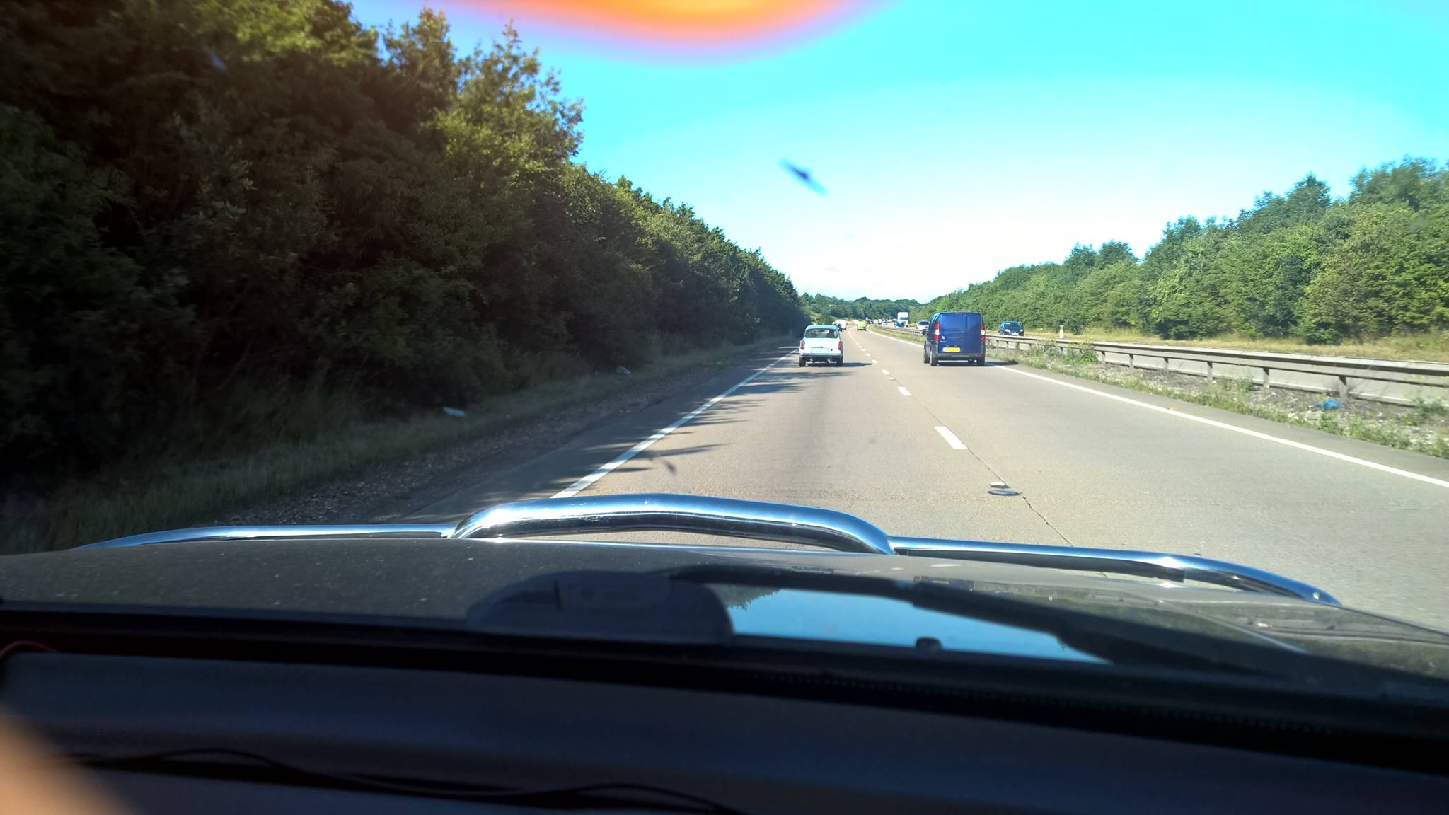
After fitting it, I took it for a pootle around town to get it up to temperature, and to check that there were no major leaks. With that trial run all good, and the temperature not going much above 90, degrees C, I took it out on a run on the motorway, to see what a period of sustained motorway speeds would do to the coolant temperature.
The coolant temperature remained somewhere between 90 and 95 degrees C at a sustained 70mph, and it actually drives better at 70mph than at 50mph! This was a triumph! I’m making a note here: HUGE SUCCESS! It’s hard to overstate my satisfaction.
However, all was not right – and about 20 miles down the road, a misfire started. Knowing I was only about 4 miles from a services, I thought I’d try to limp it there, so as to not end up broken down on the side of the motorway.
Yeah… that plan didn’t work. Another mile down the road after the misfire started, I lost all power, and the engine just wouldn’t restart.

My guess is that with the extra heat, not only the output from the better radiator, but the heat from the turbo/exhaust due to running at a higher sustained speed, one of the coil packs overheated, and therefore exploded.
When it expired, it also took out the Ignition Failure Sensor (which provides power to the ignition coils, and provides the rev counter output based on actual ignition pulses rather than “requested” ignition pulses) – so with no power feed through the IFS, that’s why the engine wouldn’t run, even on 4 cylinders.
I have replaced all 3 coils with new ones, a new IFS, and also fitted a “turbo blanket”, which has reduced the radiant heat given off by the turbo on that side.
As well as resolving this minor electrical/heat issue, I have also been tidying up the interior, and making it more civilised.
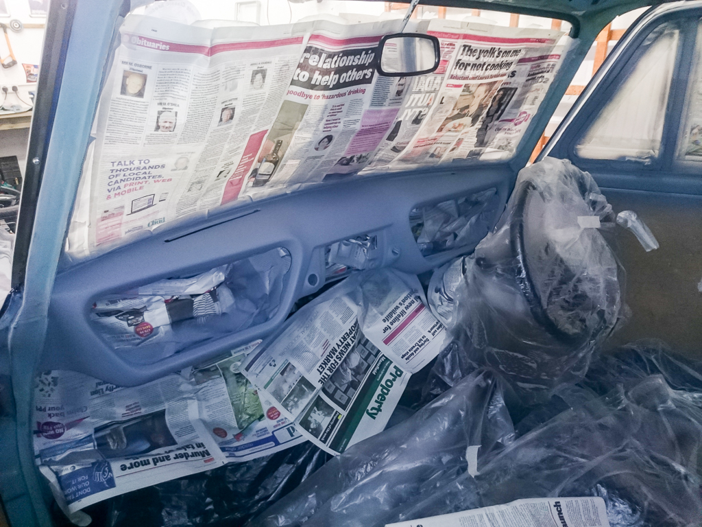
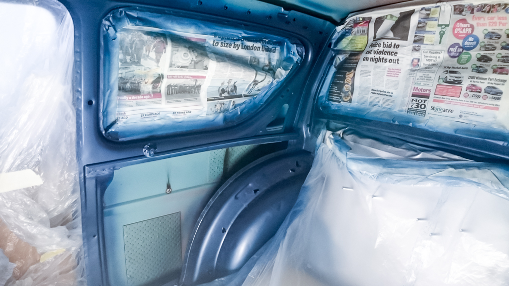
First off was to paint both the dash, and inside of the doors, around the rear windows, and fit some carpet:
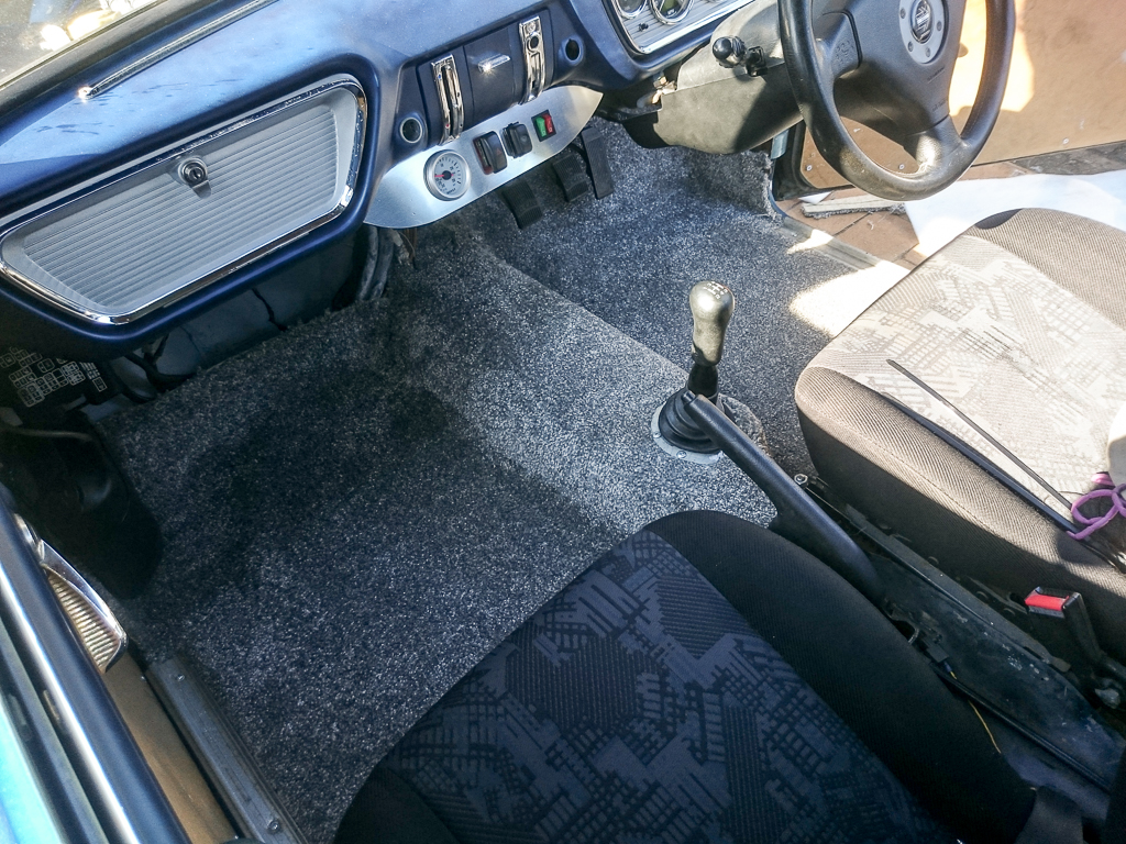
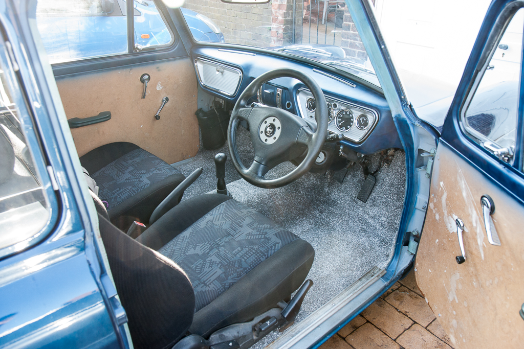
The carpet has made a huge difference to the sound levels, removing a lot of the road noise.
I also tidied up the glove box lid and dial surround with a coat of the same silver used on the outside.
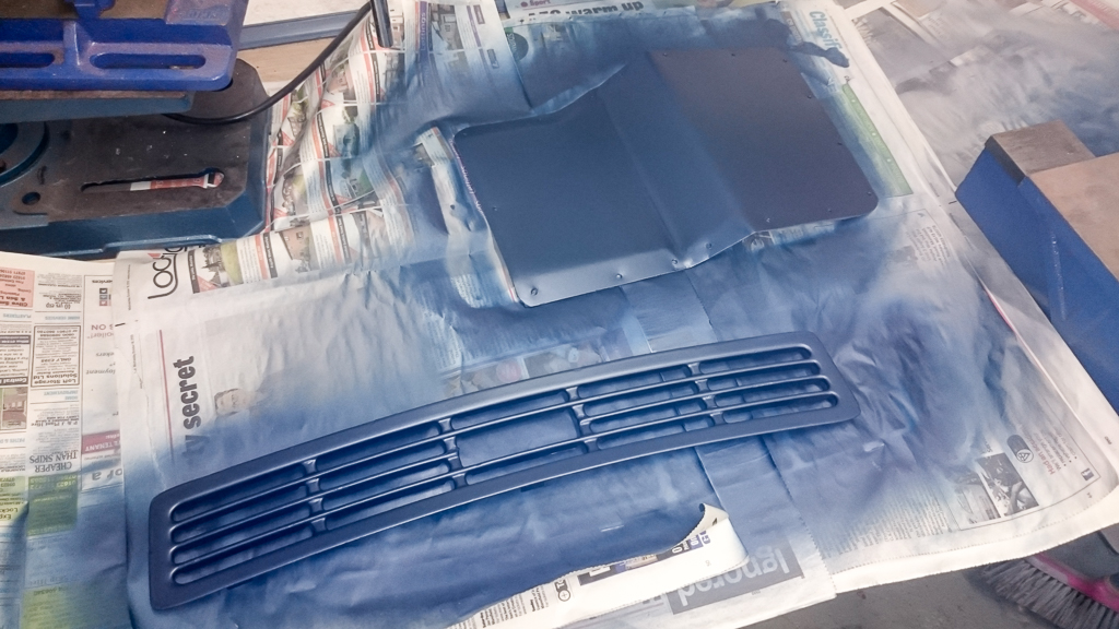
I am now finishing up the remaining bits of painting in/around the bonnet – those being the master cylinder cover, central bonnet catch bracket, and a bonnet grill.

The next thing on the list will be to make up some panels for next to where the rear seats would be, and either paint or cover them, along with the front door cards.
That will then make the interior look a lot nicer, as well as being more sound deadened. Short term, I’ll put some carpet in the back where the rear seats would be, but I do also have a couple of options for rear seats which I’ll investigate to better tie in with the rest.
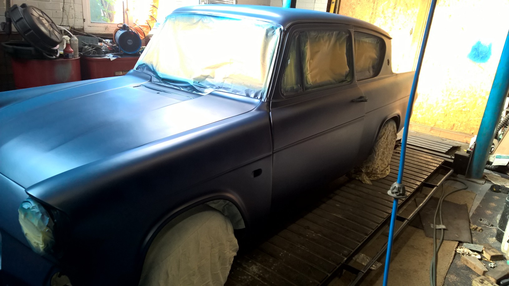
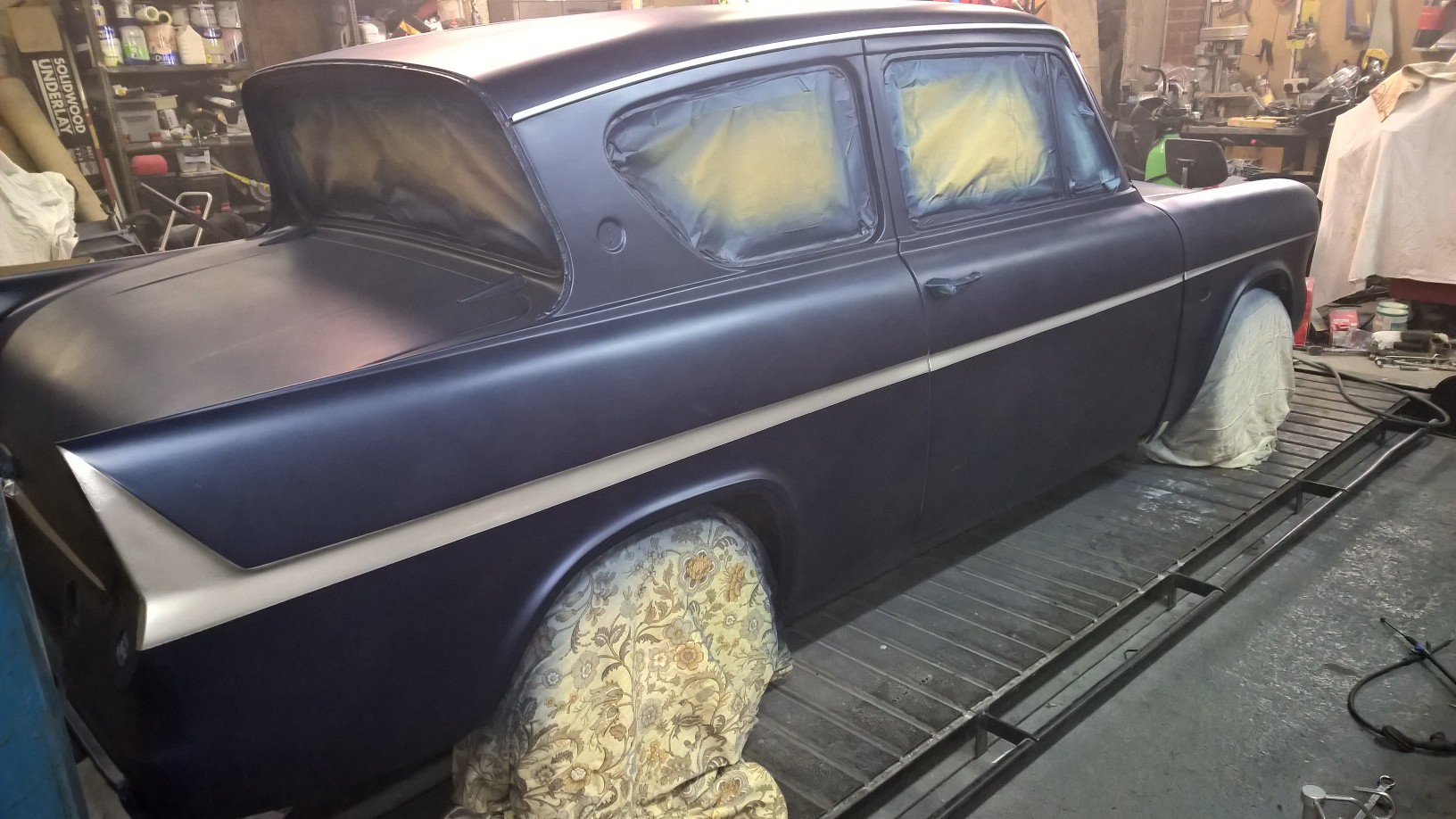
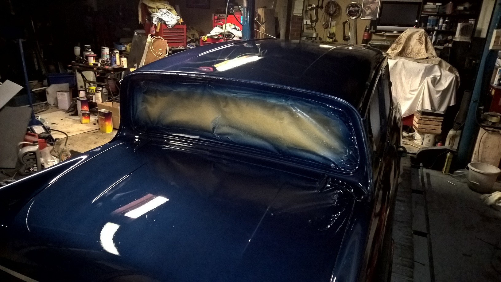
With the car successfully back at my dad’s, I left him the fun task of playing with the bodywork.
The initial coat of primer was put on before the trip to the Ace Cafe so that it was mostly one colour, and to cover the remaining bare metal.
My dad then continued to prepare the primer for paint for a few days, with lots of late nights – I did have to remind him at one point that the colour was only supposed to be temporary (and that I was taking it home soon!), he stopped with the preparation of the primer, and started laying down some colour.

With that done, next was to add a bit of detail:
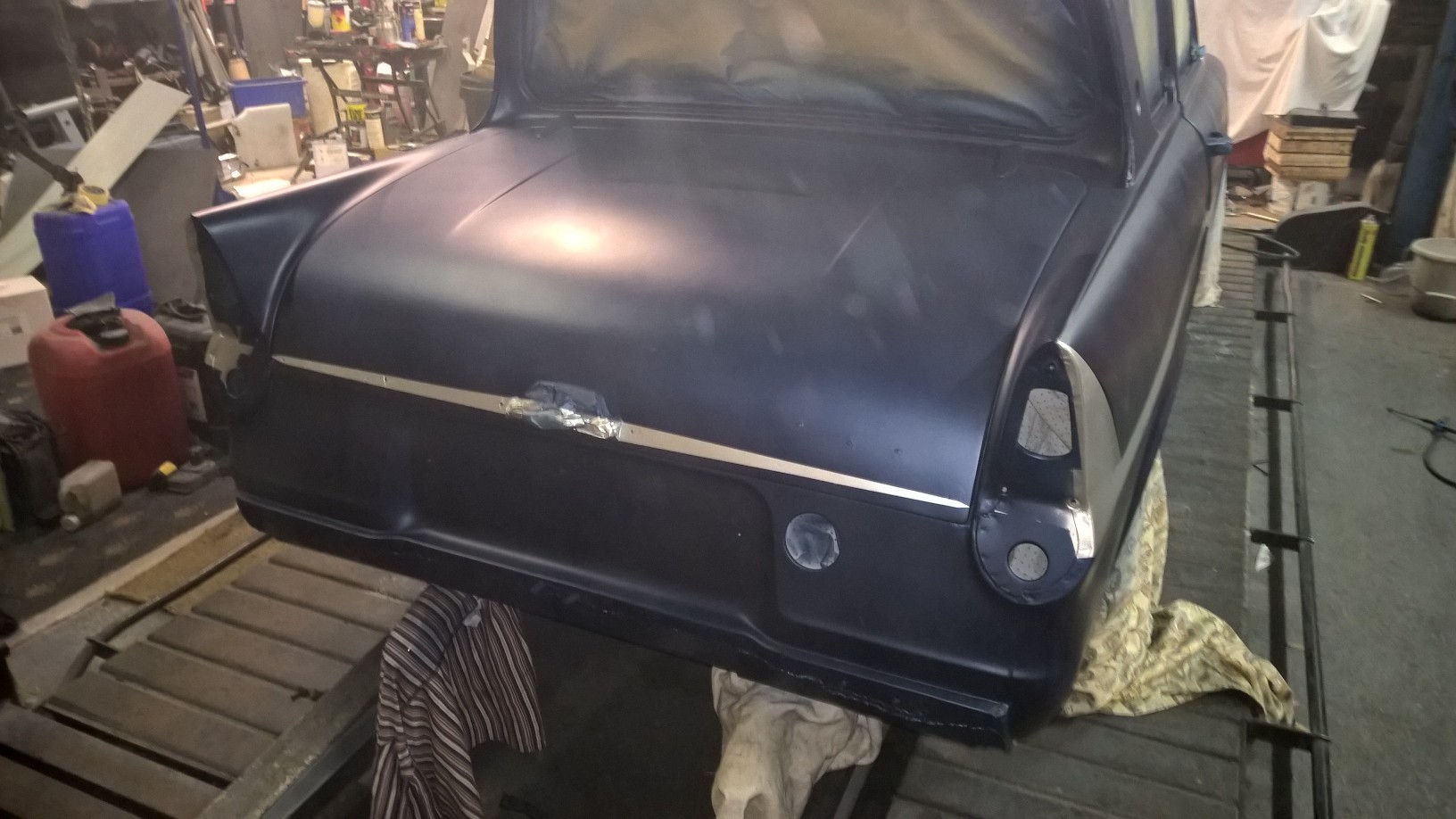

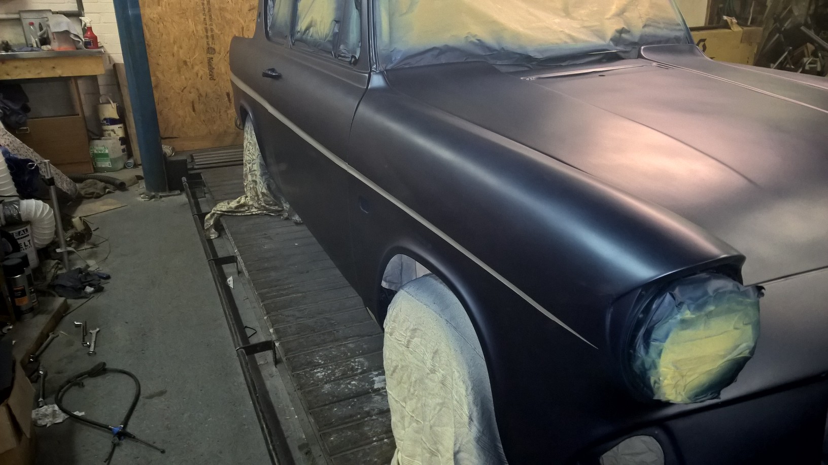
And after yet another very late night, a few coats of lacquer were added:

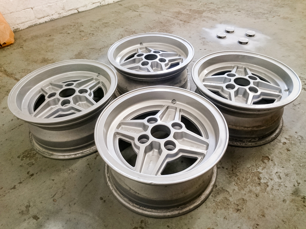
While this was taking place, I was busy at home giving a spare set of wheels a quick refurbishment:
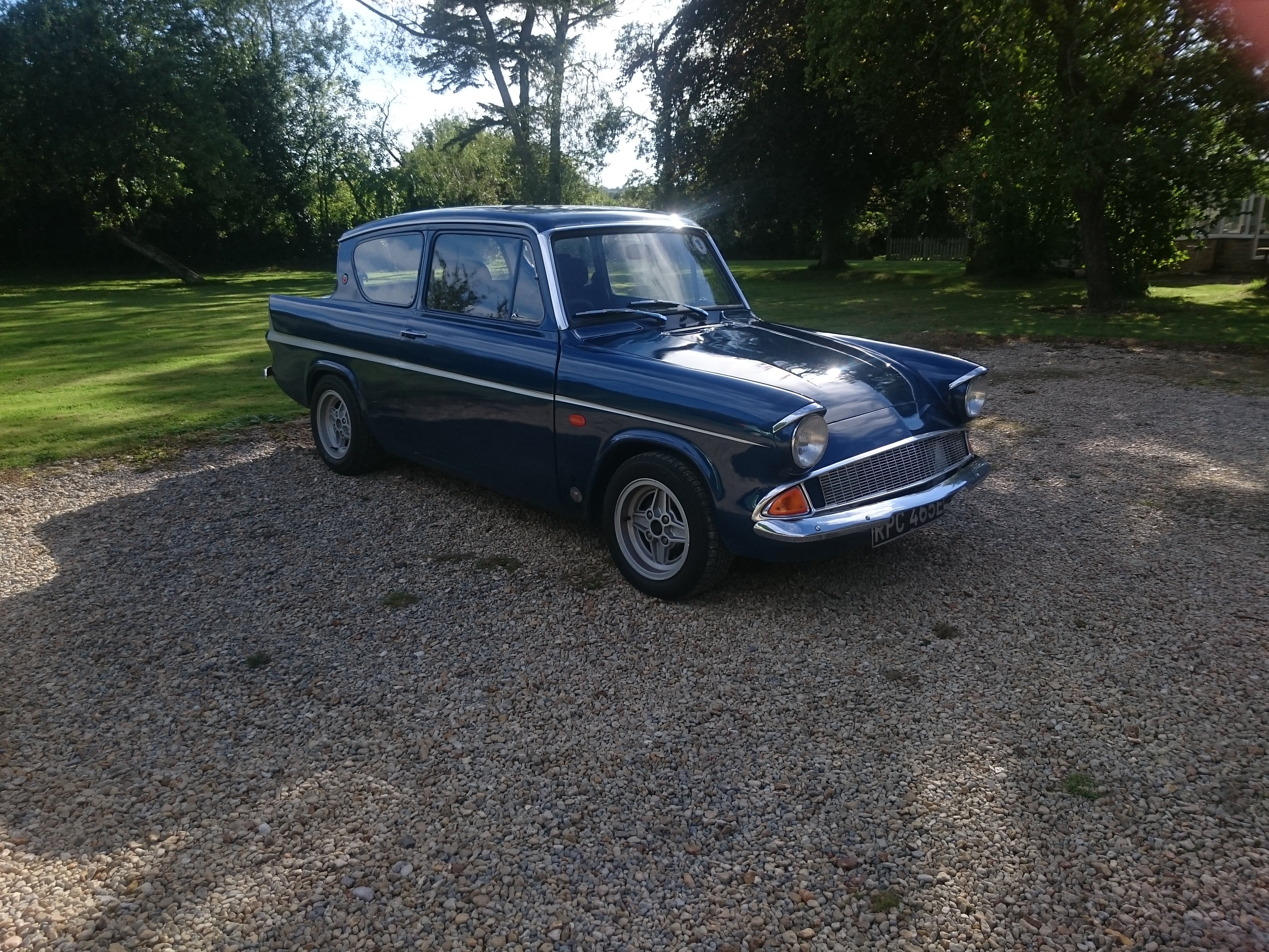
With it all together, I was finally, after many years, able to take it back home with me.
The radiator still needs to be replaced with something better, but I have now been able to begin sorting some of the small niggles, and do little bits and pieces that weren’t suitable to do during the limited time when visiting my dad.
The fuel gauge was being intermittent, so I have now investigated that, and found that the earth to the sender unit was not making full contact, so I have created a better earthing point on the sender body.
The Check Engine light had been on whilst driving, and when I had previously retrieved the error codes, it pointed towards the Crank Position sensor. Upon spending a little more time reading the codes, I had actually mis-counted the flashes, and it was the Barometric Pressure sensor. Upon investigation, I noticed that the MAP-ECU was not configured to output the Baro signal (on the original car, it was an additional sensor in the MAF, but that has been removed, so the MAP-ECU steps in again to perform this duty) – simply ticking a box in the setup for the MAP-ECU has switched off the Check Engine light!
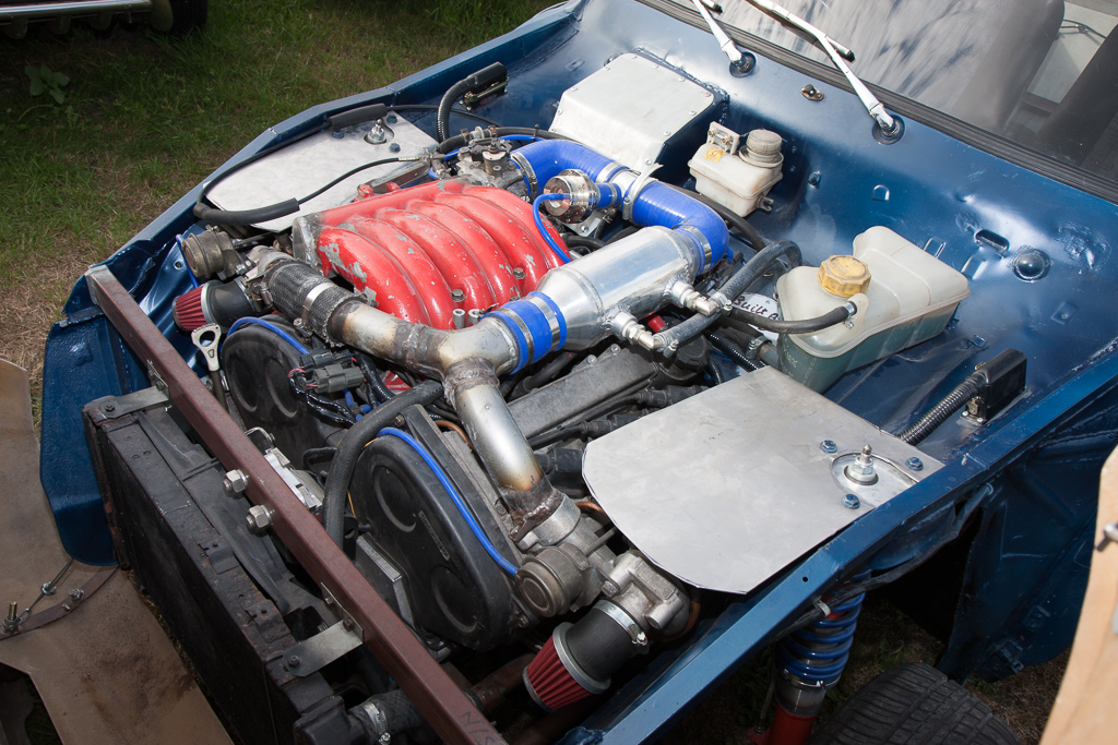
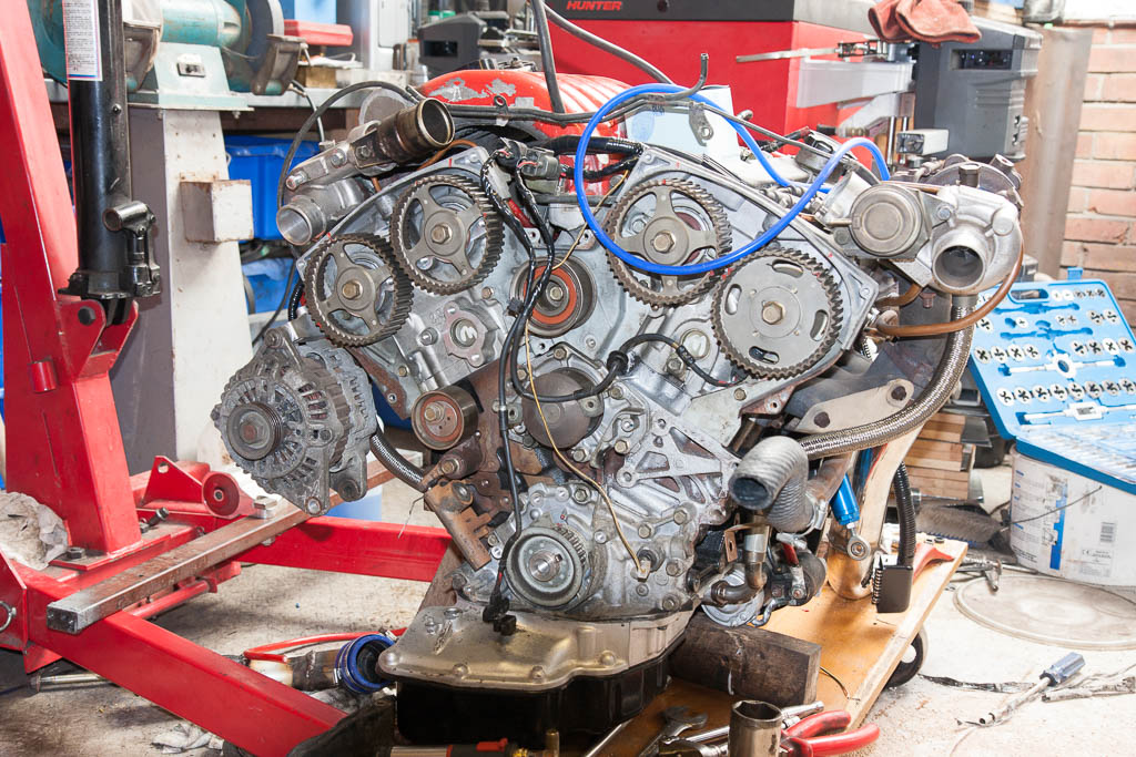
I have also finally got rid of the remainder of the red paint from the inlet manifold – something I hated from the day I picked up the donor car!
My tinkering will continue – I plan to tidy up the interior – painting the dash/doors, fitting carpet, door cards, rear seats etc, as well of course as replacing the radiator.
Prior to this weekend, it had been driven about 20 miles by my dad, and I was able to get down for a day, and in that time we have found, and had to sort the following teething issues:
Replace injectors – I fitted new filters to them, but in doing so, managed to get some dirt into some of them, which left them stuck open, pouring fuel into the engine!
Tweak the ECUs – the MAP-ECU appeared to lose some of its configuration, meaning that it was not actually giving a signal to the standard engine ECU for air flow! So the first 5 miles or so, it was running only on the “fail safe” fueling!
Replaced all the spark plugs, as it was missing under load.
Discovered that the tyres on the back are awful, as under power, it was pulling quite hard to the left, and to the right under deceleration. Swapping the rear tyres side to side improved it, so a new pair of tyres had been ordered and been fitted.
The PLX wideband O2 sensor control unit has failed, so it’s not putting out the correct voltages on either the wideband output, nor the simulated narrowband output. This has been removed, and replaced with the stock narrowband sensor until I can afford a new wideband controller.
With the annual “Anglias At The Ace” happening the weekend just gone, and determined to get there, I went down and spent last Thursday night and Friday doing some more to make it ready. My dad had done some more filling & sanding, getting the car ready for paint. However, with life getting in the way, by Thursday it was only nearly ready for priming – so Thursday evening was spent finishing off the sanding back, and giving it a blow over with primer – which was finished at 12:15 on Friday morning!
Friday morning I got up early, and spent the morning undersealing the car – if we were taking it on the road, the bits we’d previously welded and primed needed some better protection. So, after masking up all the bits I didn’t want to get covered in underseal:

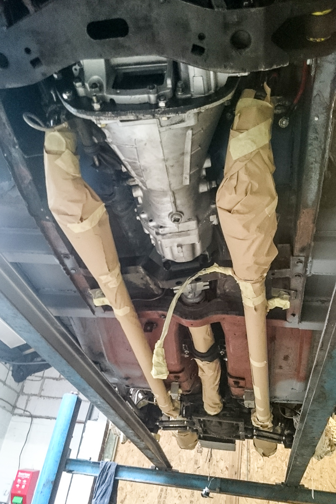
I covered both myself and the underneath of the car with underseal:

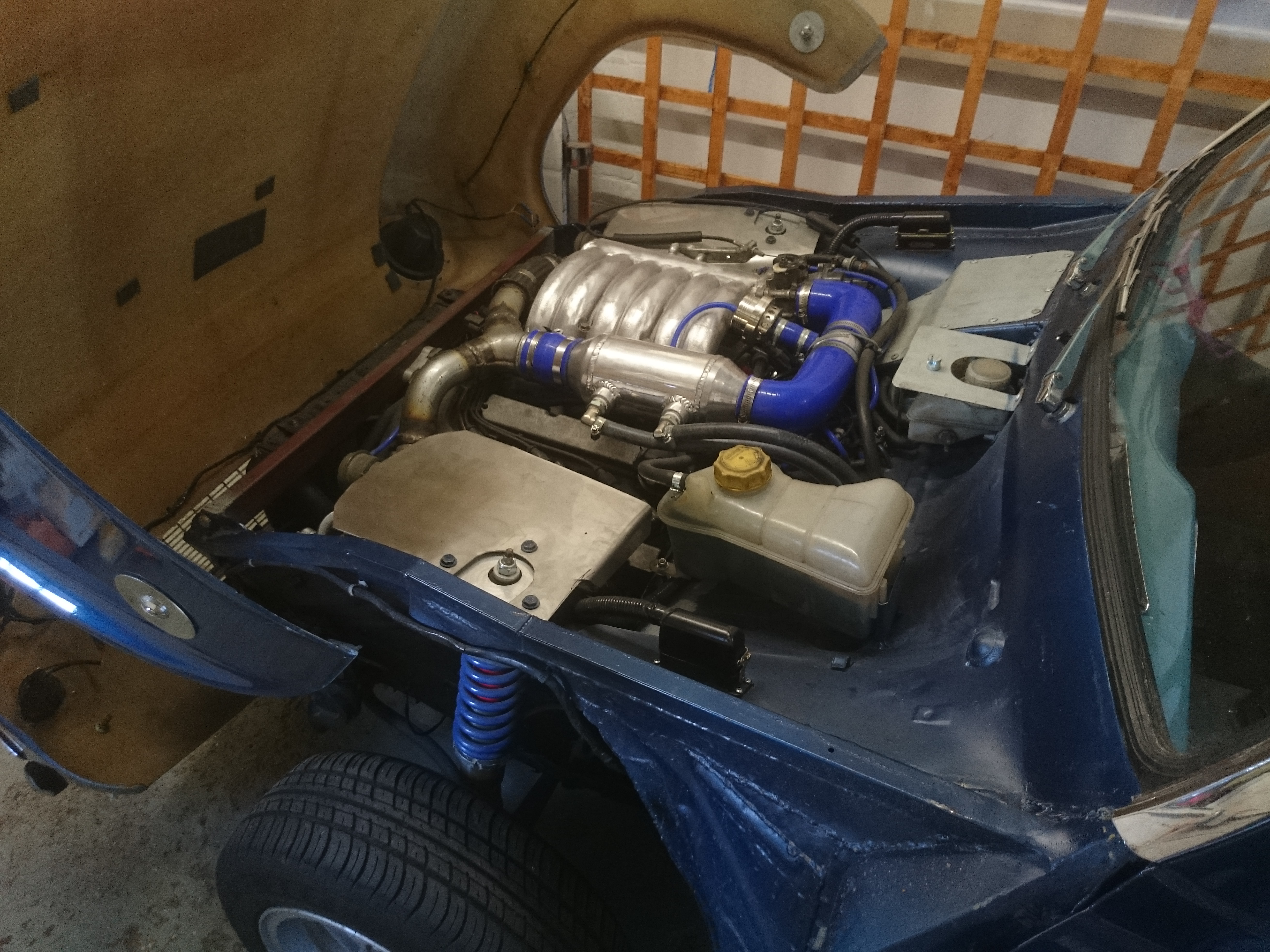
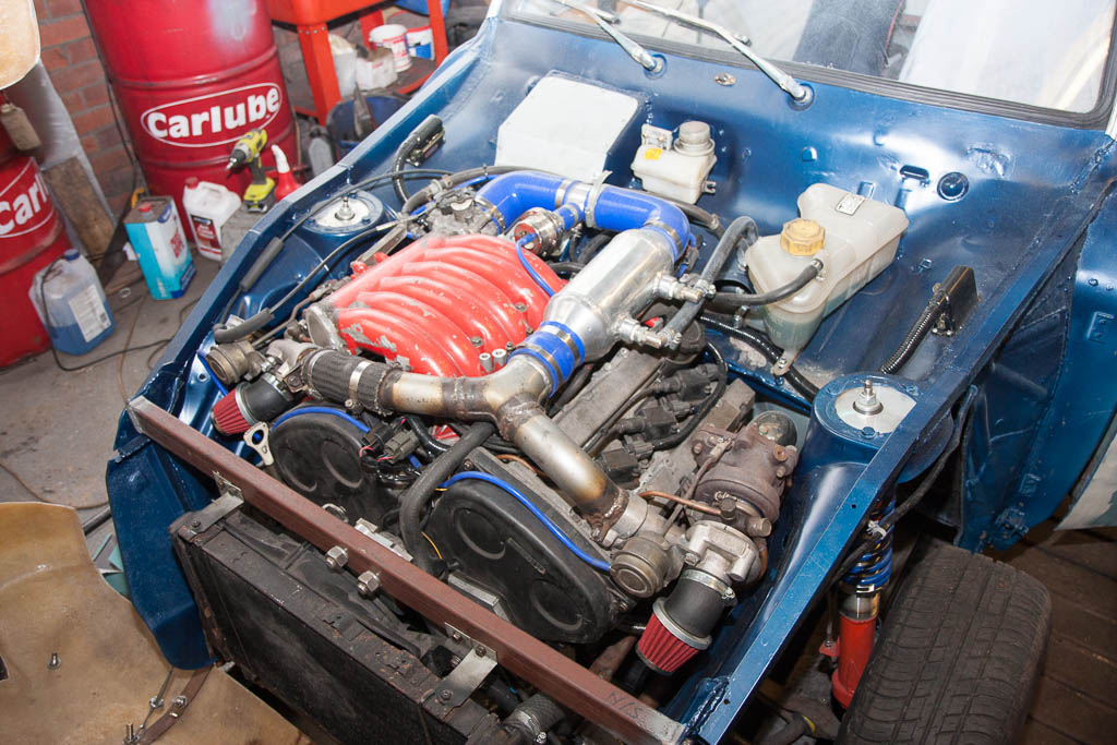
During the small amount of driving it had done, we noticed that the bonnet got VERY hot right above the turbos – so something was needed to reduce the heat transfer into the fibreglass. With a sheet of nice thick stainless steel, I made up some heat shields to cover the turbos, bolted onto the strut tops, so that the heat is transferred into the rest of the body.

With all that done, and just 25 miles on the odometer, it was time to firstly give the interior a good hoover out as it was covered in filler dust, and then take it out for a bit of a longer drive – firstly to see if the new tyres made a difference to the handling, secondly to see if the heatshields had made a difference before the “long” drive to the Ace Cafe, as well as to shake down anything else that we’d not picked up yet.
Given that I’d only driven it about a mile so far, I went out onto the road tentatively, and all felt good. As I started to become a little more confident, and the engine came up to temperature, I pushed it a little harder, until I was trying out some full-throttle runs. However, here is where I found an issue – it pulled great in 1st and 2nd all the way to the red line (no pulling to the left now the new tyres are on), but in 3rd and 4th, it got to just over 4000rpm and hit a rev limiter.
Came back, and got the laptop out and hooked it up to the ECUs to check the configuration. Nothing jumped out at me, so went out for another drive to save some log files for looking at later. There was also a small “chirping” coming from the back, which was related to road speed, that disappeared when lifting the handbrake slightly. Got it back home with the odometer now on a huge 49 miles!
I did find when looking through the logs that the original Mitsubishi ECU thought that I was doing over 400km/h – I certainly wasn’t doing that!! I then remembered that the speed limiter on the ECU can’t be removed, but it can be increased to 255 MPH – which is 410km/h!
So, with it being late on Friday, on Saturday morning got out early, cut the speed sensor signal to the ECU, and removed the rear wheels to back off the handbrake slightly.
With that done and back on the ground, we set off for our drive to the Ace. As this was the furthest from my dad’s post code it has yet to be driven, we decided it safe for my dad to follow me in his Shogun with a trailer and a boot full of tools – just in case anything was to go wrong or not feel right, we could simply load it up, and deal with it later.
Heading off down the road, first I noticed that there was no more chirping from the back end. Getting onto the dual carriageway, I gave it full throttle in 3rd, and it revved straight past 4000rpm and to the redline – so it obviously was the engine ECU engaging the speed limiter at 4000rpm.
I had to pull over about half an hour and 25 miles after leaving home, however. As dad pulled over behind me, he gets out the Shogun with a worried look on his face as I walk towards him. “Can I have the duct tape, please?” I ask. “The chrome surrounds for the heater controls, and the ashtray are rattling, and it’s annoying me”, I add.
After taping up the rattling trim, the rest of the journey to the Ace was completely uneventful.
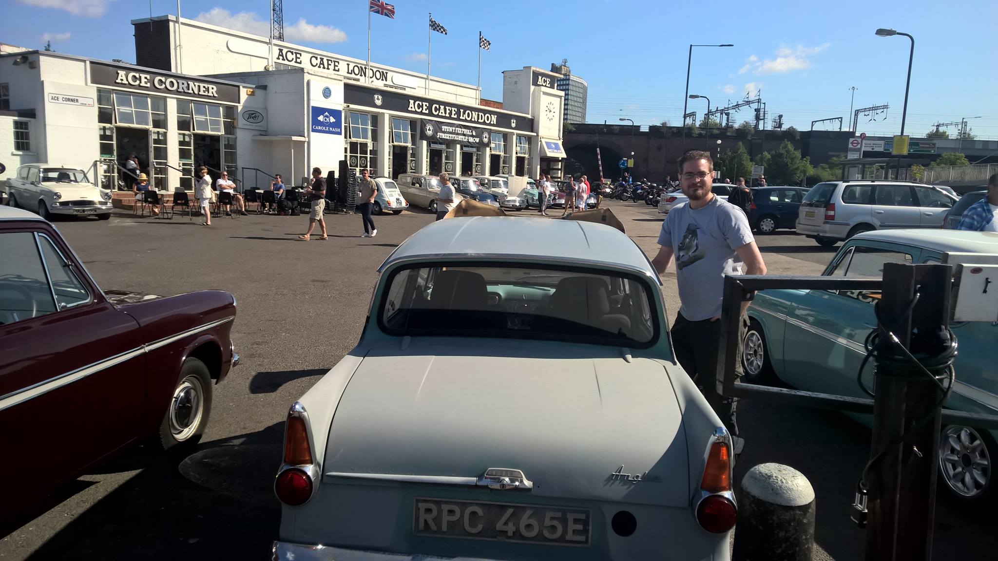
Another great day, met and chatted to plenty of lovely people, and saw 49 other lovely Anglias!
Then I drove it back home without any more issues, pulling up back at my dads with 210 miles on the clock. On a run, the engine coolant temperature gets a little higher than I’d like it to be, so (as was always expected) a better radiator is required for more serious running – but it’ll sit happily at 70mph without overheating as it currently is.
It’s only running at about 6psi of boost at the moment (I’m hoping I can get around 14psi out of it), so it’s not quite as quick as it could be, but… even with that, it’s rather quick! Using the timers built into the gauges, and still not *really* pushing it too hard yet, it’s given so far a <7 second 0-60, and under 17s quarter mile. Just need to get it tuned right, get the launch control set up, and get it to a drag strip to see what it can really do!

This update comes courtesy of my step-mum, who suggested that my dad booked a week off work to spend purely on the car! Thankfully, my girlfriend also thought it was a good idea, and so this is the culmination of a week’s work! The last full week I had on the car (back in November 2011!), we made loads of progress – would this week be as productive? Read on to find out!
As the suspension mounts have been moved onto the diff carrier, the mounting points needed reinforcement. The rear mounts had already been reinforced, so we did the fronts, they now bolt through some nice heavy box section.

Where we had to cut away the bulkhead for the water pipes off the back of the engine, this needed replacing, so a new panel was made up. Originally we planned for this to be removable to gain access to the water pipes – but with the engine so simple to take out (less than an hour), there’s really no point, so it’s welded in for no loss in strength.

It was always to plan, once we’d proved that the brakes/clutch worked OK to replace the temporarily made push-rods with new ones, made from a single piece of metal, rather than the extended temporary ones.

Being a 1967 (and, of course, for safety), it needs seat belts in the front. A pair of inertia-reel seatbelts have been fitted, which are much better than the original fixed belts!

Having had the car running and driving for a while (only as far as in/out of the garage, and on/off the trailer), we noticed that the coolant level was dropping, and the oil level was increasing… so, the engine/gearbox came out, and it had a pair of new head gaskets, a set of 24 valve stem seals, new lower inlet manifold gaskets, and new injector seals/filters.

Whilst the engine was out (hopefully for the last time for a while!), the bare metal and welds were given some protection.
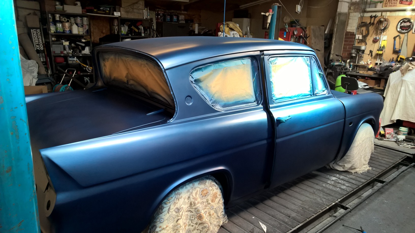
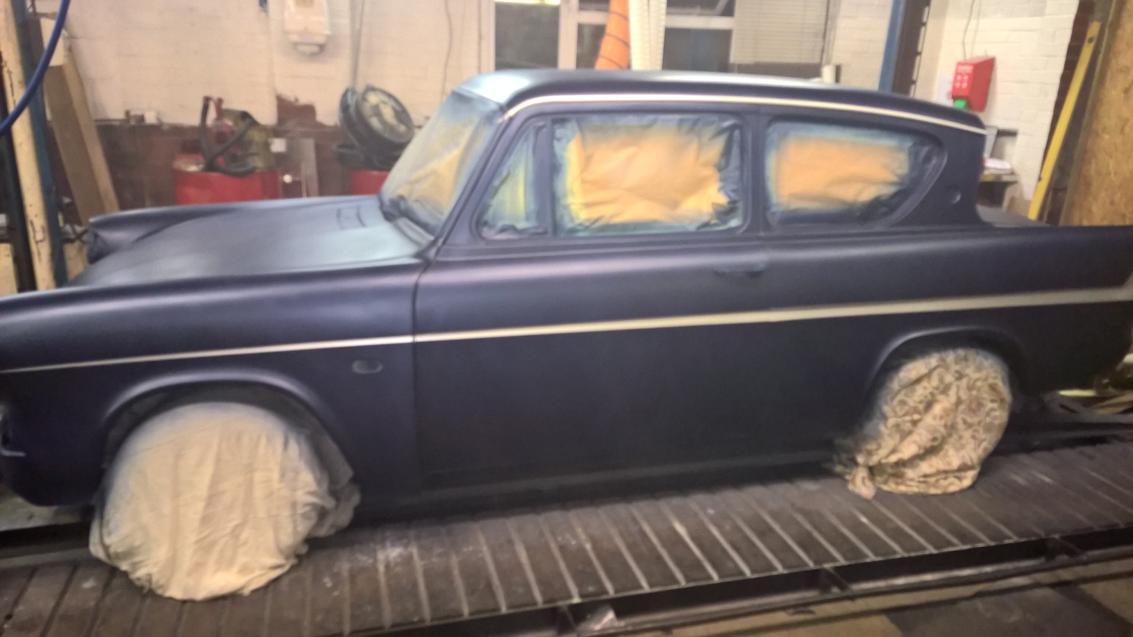
Not having enough of a single colour in the cupboard, we mixed together 4 different colours: Mitsubishi Fiji Blue pearlescent, Mitsubishi Twilight Blue metallic, Ford Java Blue metallic and Vauxhall Lagoon Blue metallic. So even the paint is a hybrid of various makes! (The flash makes it look a little lighter than it is in daylight – that’s all the metallic/pearl bits catching the extra light from the flash)
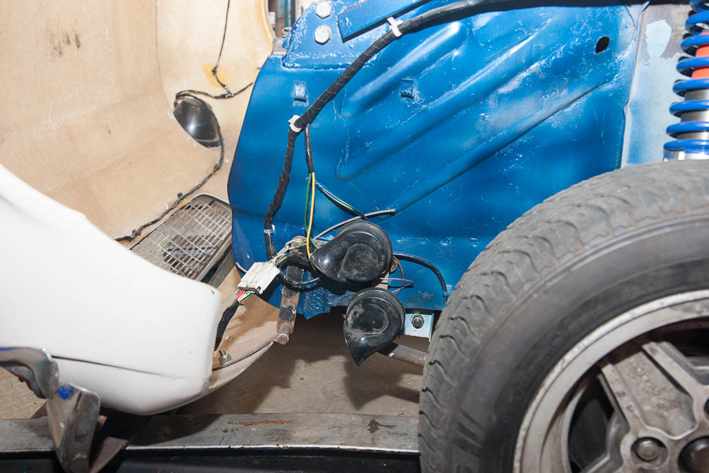
Meep meep! A pair of horns scavenged from a scrap BMW.
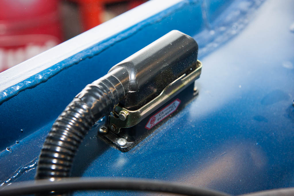
I mentioned before the new connectors for the engine – there’s one of these on each side of the engine bay. So to remove the engine, we simply needed to unclip these two.
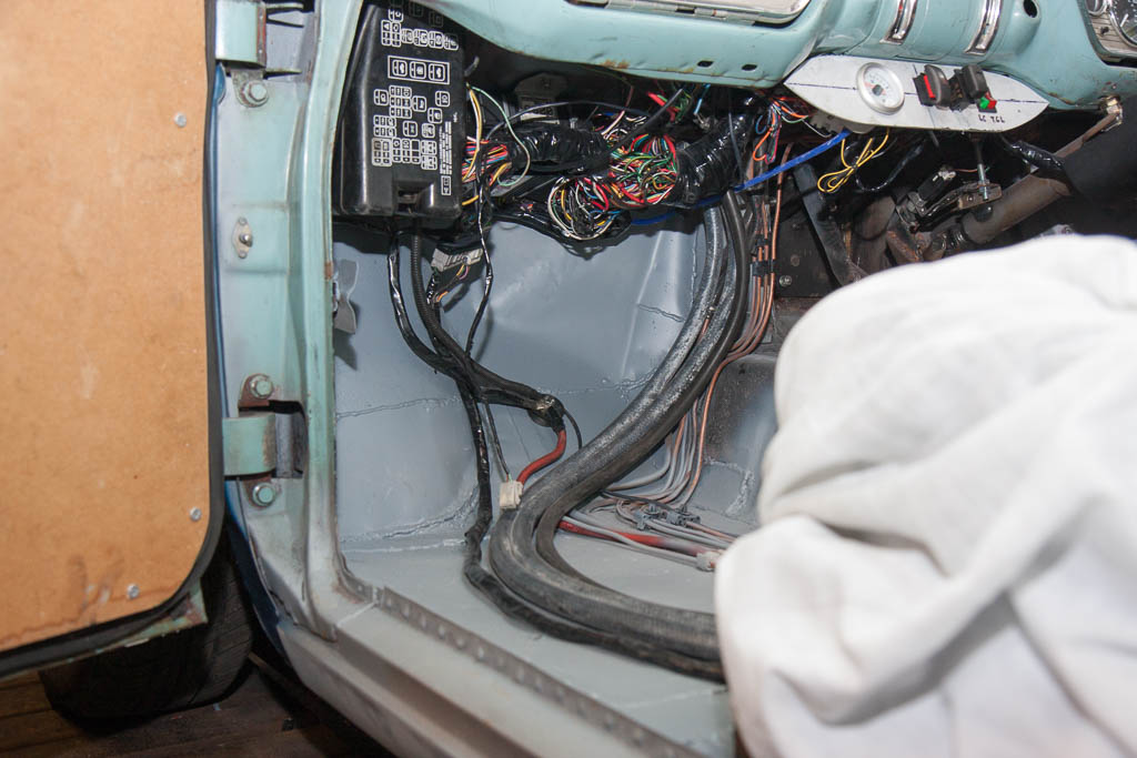
All the wiring inside, now completed, has been tidied up, tucked properly under the dash, and a panel was made up to house the boost gauge & various switches (hazard warning, heated front screen, clutch servo solenoid and launch control)

Then came the moment of truth – an MOT test! With everything put together, checked and double-checked, we took it for a fresh pair of eyes to give it a thorough check over. A nervous wait followed whilst the tester looked, prodded, pulled and poked at everything they usually look at, prod, tug and poke during an MOT test.
He then wandered through into the testing area, and presented a piece of white paper (I miss the days of coloured paper, where you at knew what the result was from across the room without having to read it!) – “Refusal of an MOT Test Certificate” was what this one was not titled! Instead, it said proudly at the top of the sheet “MOT Test Certificate” 😀
Having sorted insurance a couple of hours earlier, I fired up the vehicle licencing page on my phone, and promptly taxed it and drove it back home!
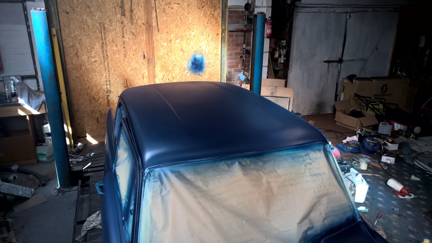
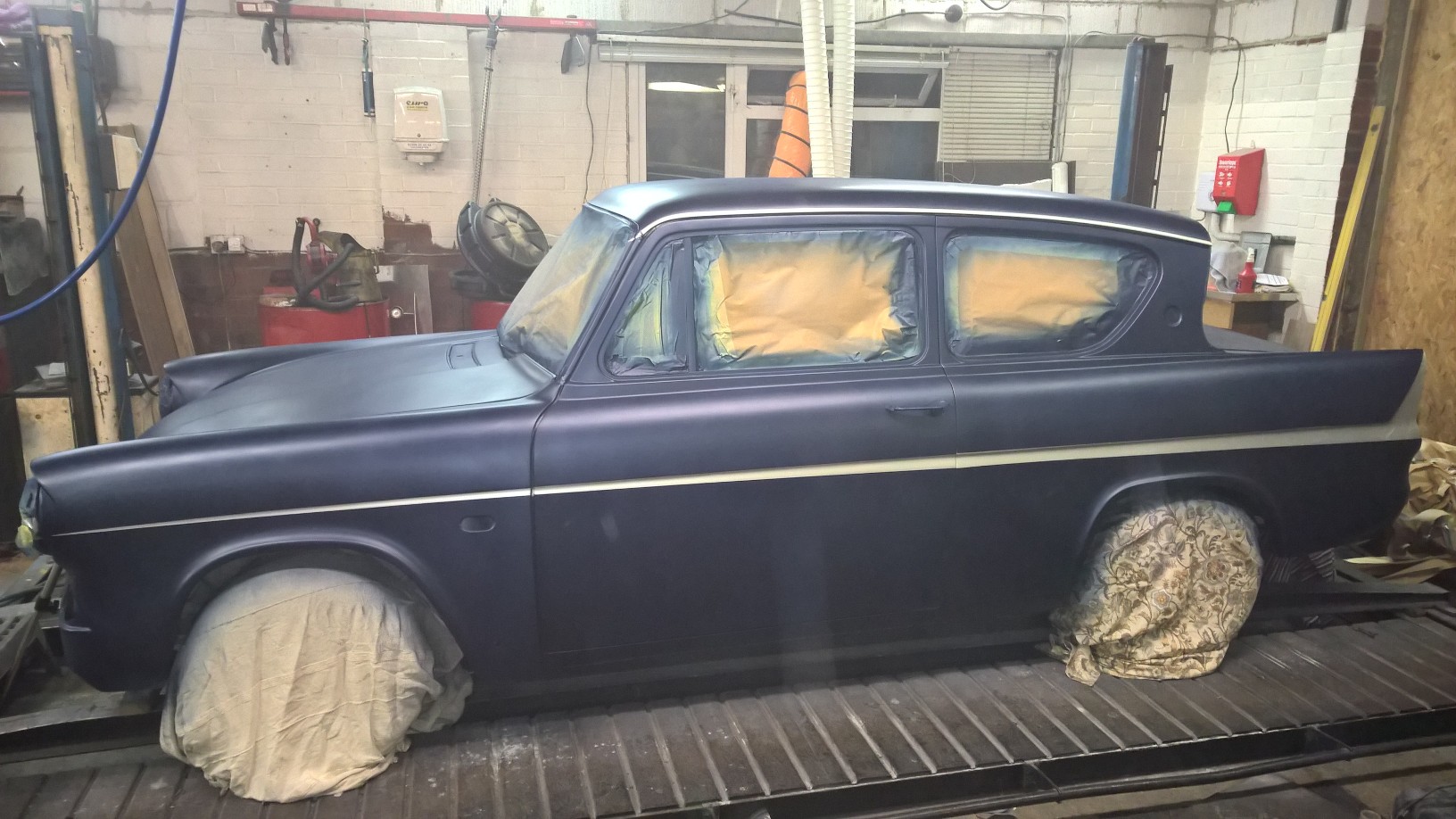
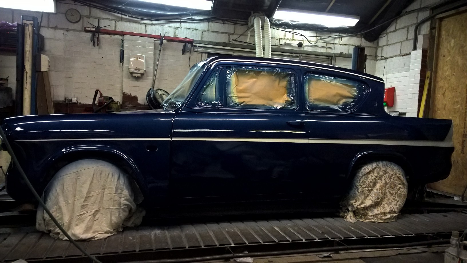
So – how far has it now been driven? Well… back home… where we then proceeded to start on tidying up the bodywork! Having seen the blue in the engine bay, we decided that, as there was some bare metal that still needed protection, to give the whole car a blow over with our newly created colour. All the bits of surface rust have been ground back and treated, the holes for the side trim (which isn’t going back on) welded, ground back and filled over.

Next is to smooth back this filler, and give it a quick coat of primer & paint so it’s all a single colour, and protected for now – until it comes off the road again in a few months to be stripped back to a bare shell to have a full, proper fix of bodywork and paint.