The next task is to make up the suspension arms – 3 per side. 2 for the bottom, 1 for the top.
As with the trailing arms, these consist of a length of steel tube, threaded inserts, locking nuts, and rose joints. One rose joint is right hand threaded, the other is left hand threaded, and this allows fine adjustment of the length of the arm, without needing to remove anything from the car. Simply loosen the locking nuts, and rotate the tube to lengthen, or shorten, the arm as necessary.
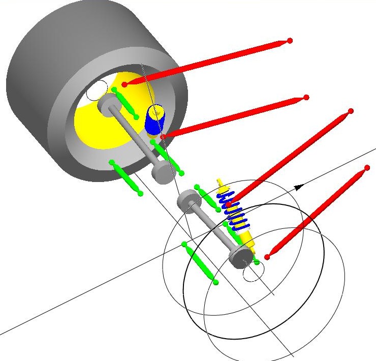
This gives the ability to fully adjust every aspect of the suspension – the toe (whether the front of the wheels point inwards or outwards, and by how much), the camber (how far from vertical the wheels are), and the position within the arches.
We started by making the arms to the correct size needed to put the wheels in the same position as they are with the De-Dion. When looking at it on the car, I’d decided that the wheels were too close to each other, and ideally needed to fill the arches more – so basing the arm lengths on getting it as it current is, will allow adjustment outwards to where necessary (there’s about 5cm of length adjustment on each arm, whilst still maintaining a suitable amount of thread within the insert – which gives up to 10cm overall width adjustment on each side… plenty, as it only needed to come out by about 2cm each side to really fill the arches)
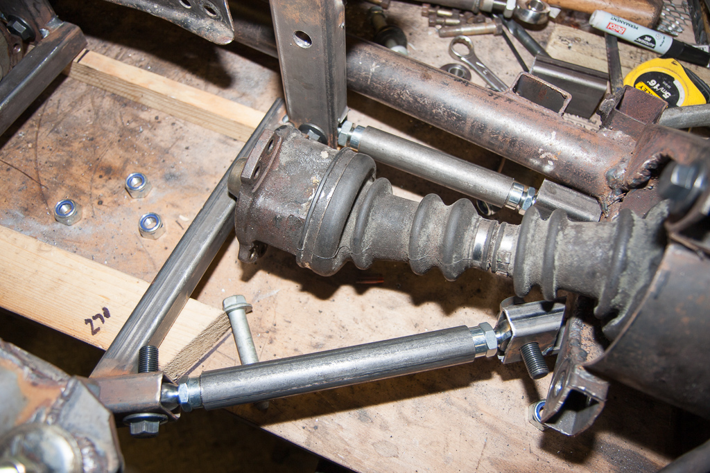
So, we made up the lower arms on the bench:

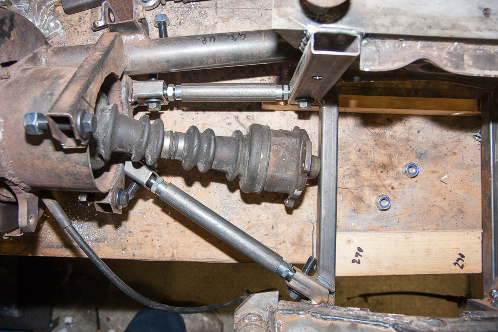
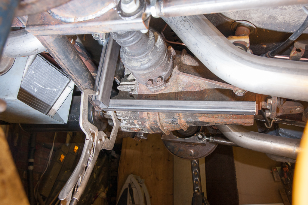
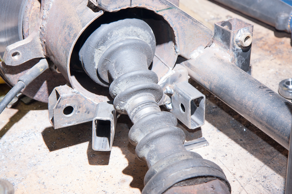
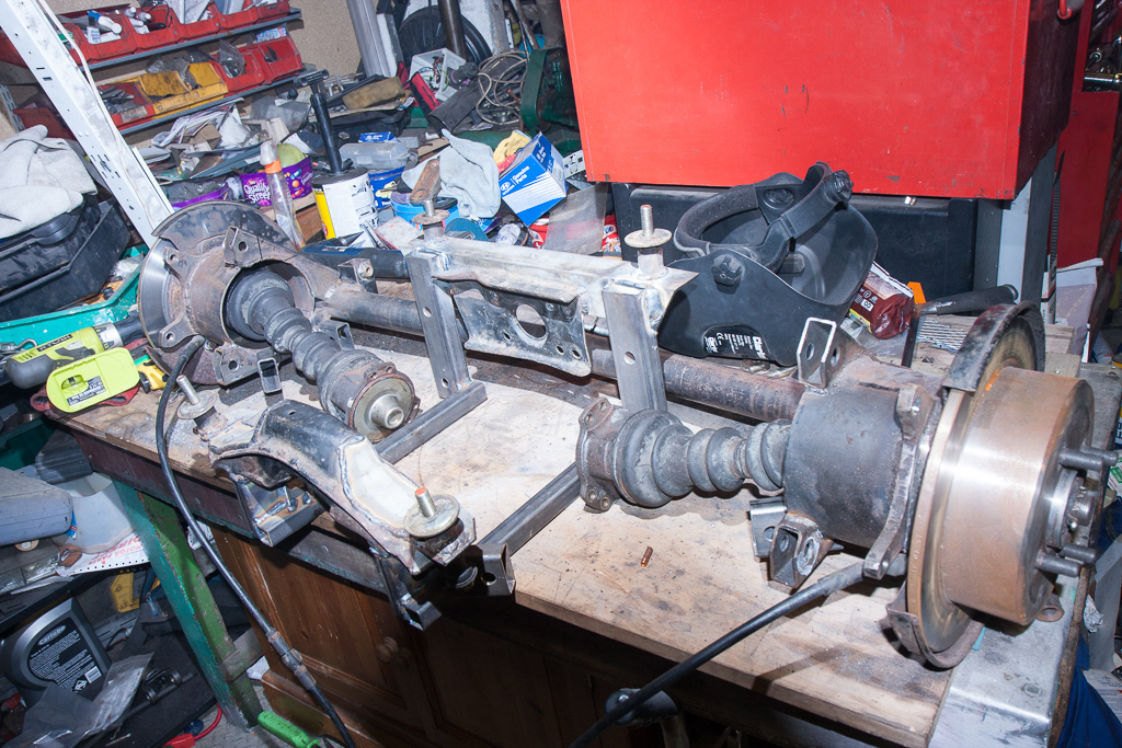
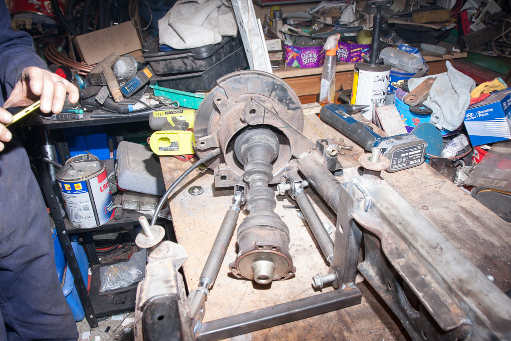
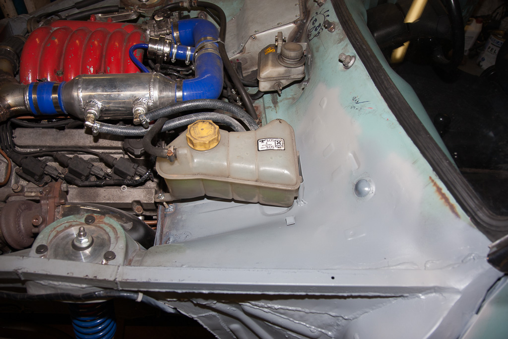
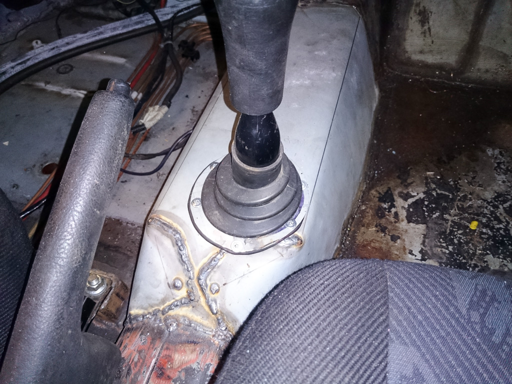
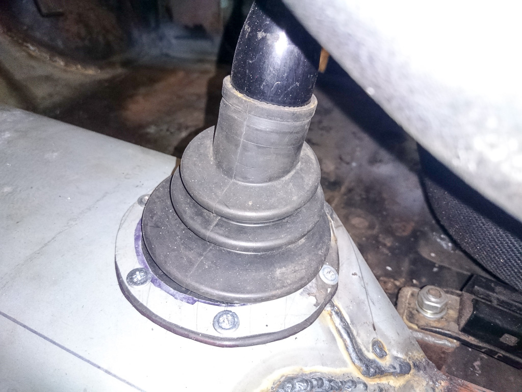
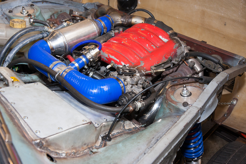
To get the correct length and position for the upper arms (avoiding the exhaust), we then began to transfer stuff to the car, firstly re-fitting the diff and carrier.
The next bit I forgot to photograph, so I’ll try to explain what we did. We reattached the existing De-Dion axle, including the new lower arms, made up the top arms to length, and then removed it, and chopped the hubs off from each end of the De-Dion tube. This then gave us the hub units separately – our first step towards making them independent.
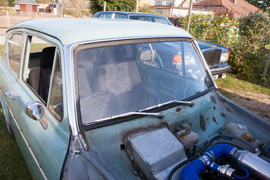
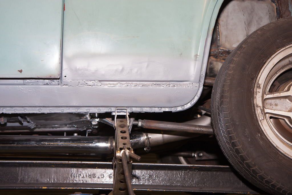
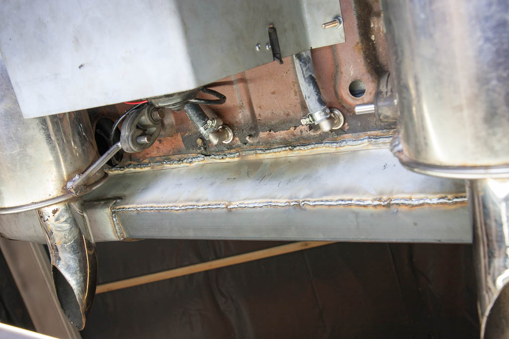
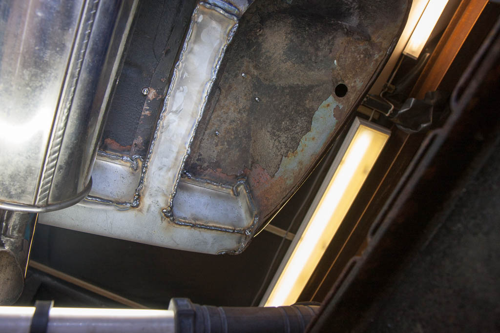
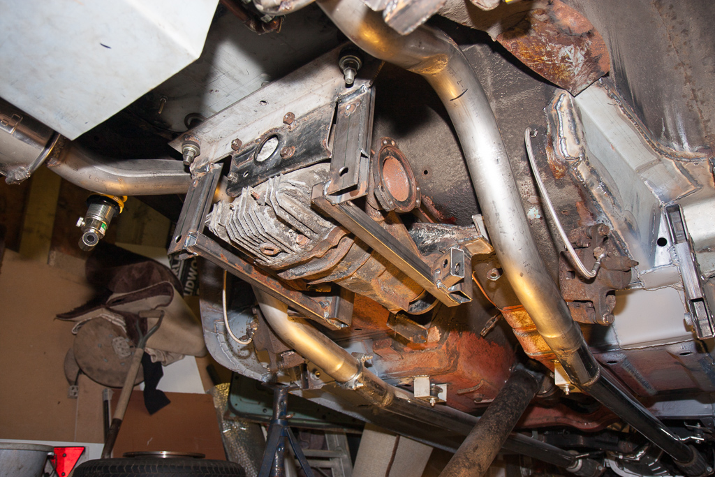
We needed to give a slight tweak to the exhaust pipes to give us clearance for the top arm – we could have curved it under the exhaust, but as the legendary Colin Chapman allegedly would have said, they then would have been “pre-failed”. But, we’ve got enough capacity in the exhaust to be able to sacrifice a small amount of volume!

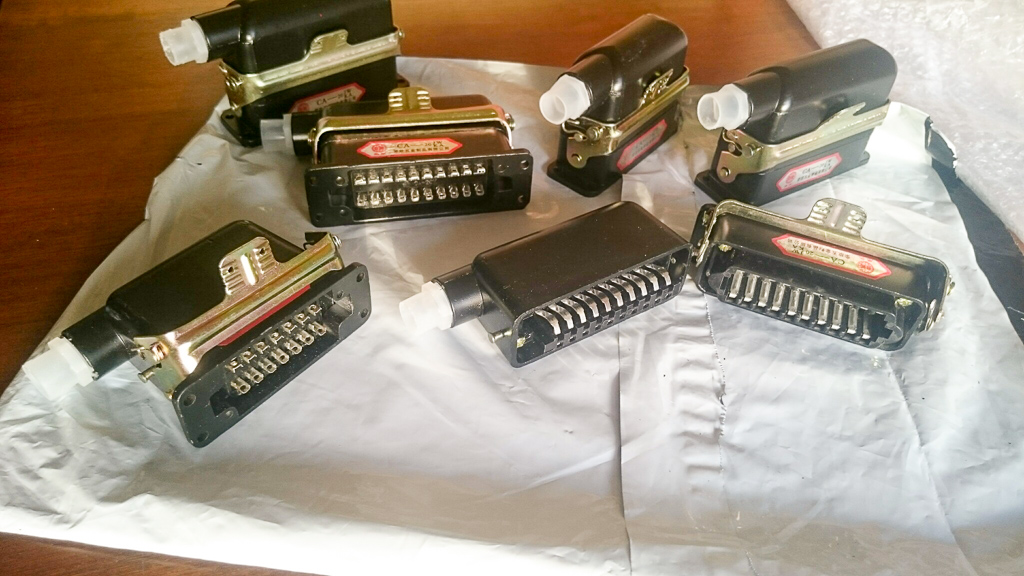
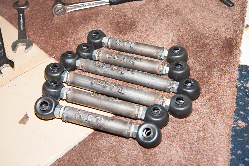
So, with the welded (and labelled) suspension arms:
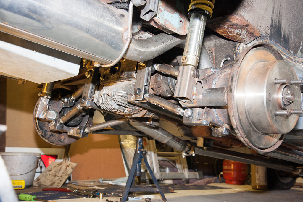
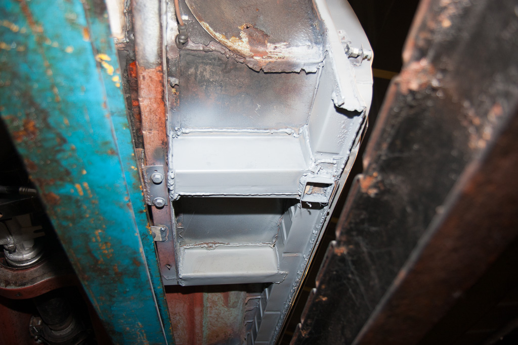
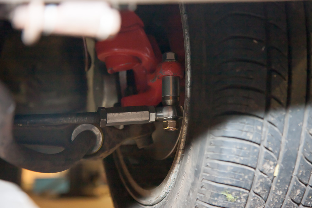
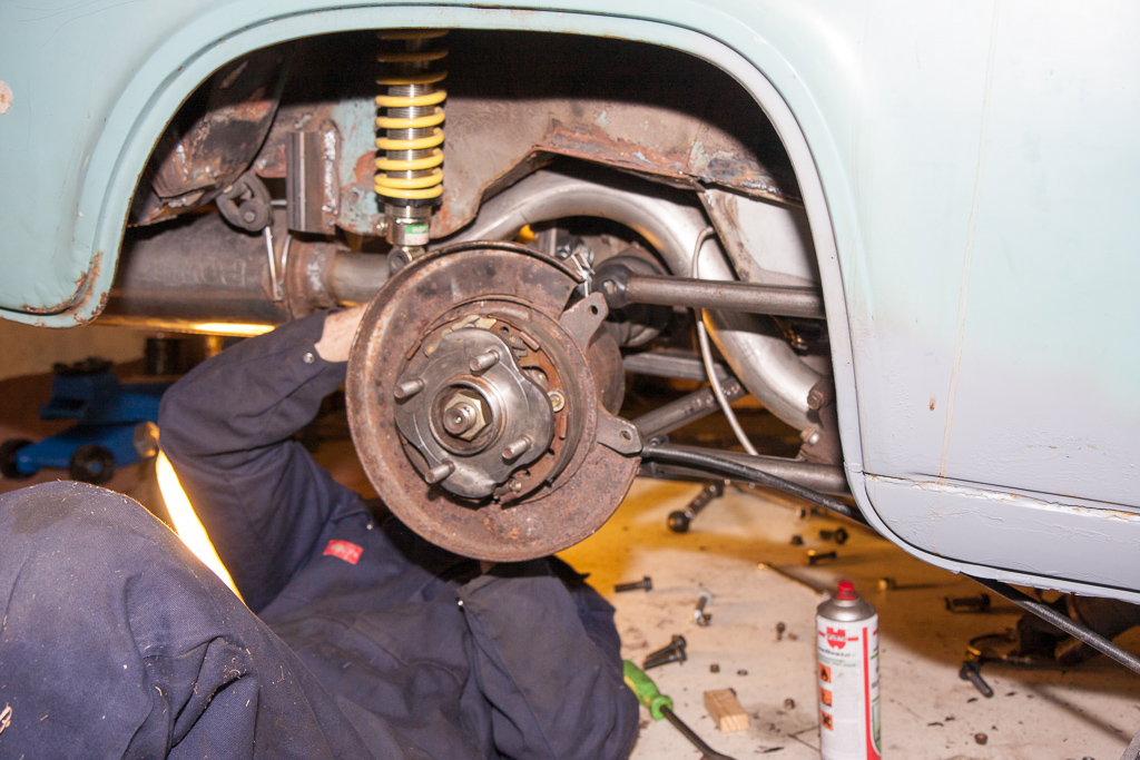
We began to attach each hub unit. First the two trailing arms:
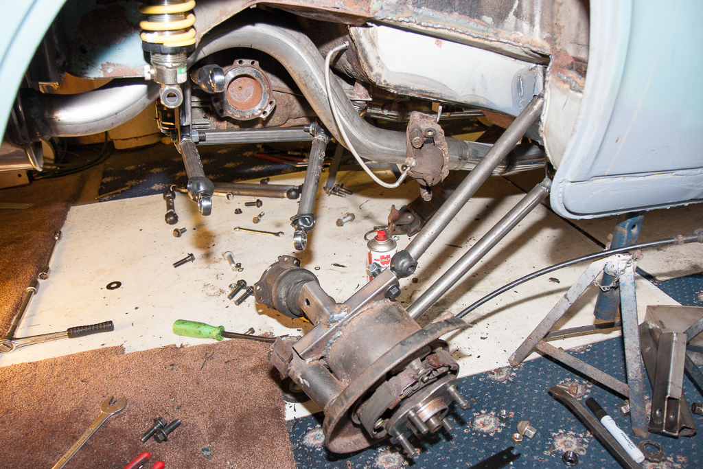
Then the remaining arms (as you can see, I was extremely useful here, and took it upon myself to take photos, rather than help hold the weight of the hub!)
The rubber boots for the rose joints actually ended up causing us the most hassle – we’d used 25mm box section, which the bare joints slotted into perfectly. With the addition of the rubber boots, they just wouldn’t fit right. So, we decided to use them slightly differently to how they are supposed to be used, and instead cut the end off them, and stretched them over the box section and over the nuts/bolts – just as water/dust tight, and much easier to fit!

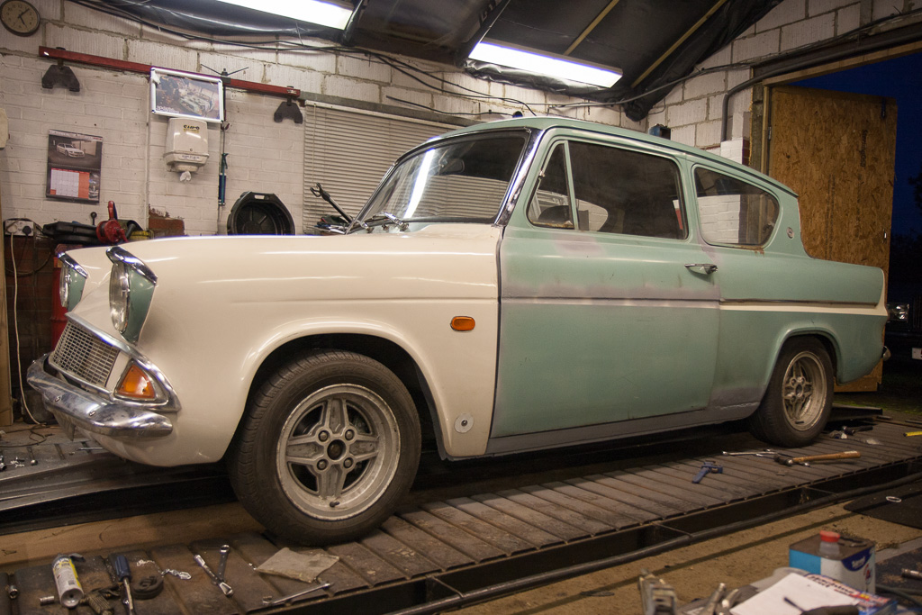
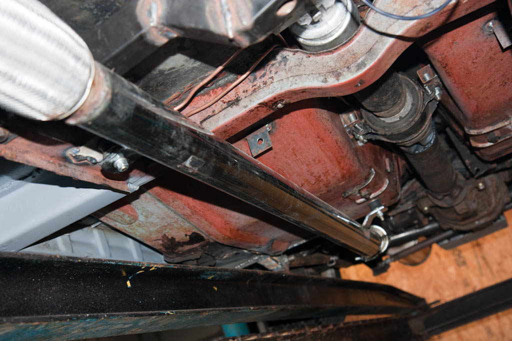
So, with both sides attached, this is how it looks with full droop: