Propped up and shafted

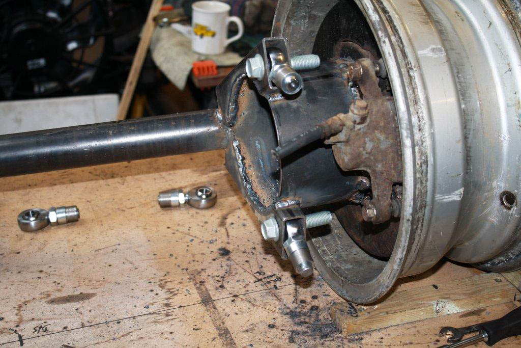
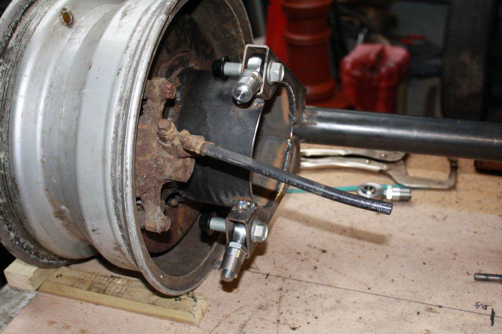
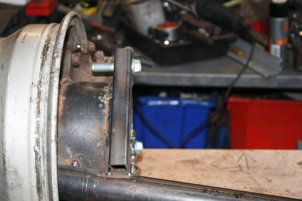
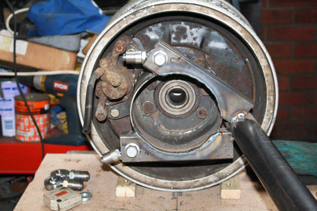
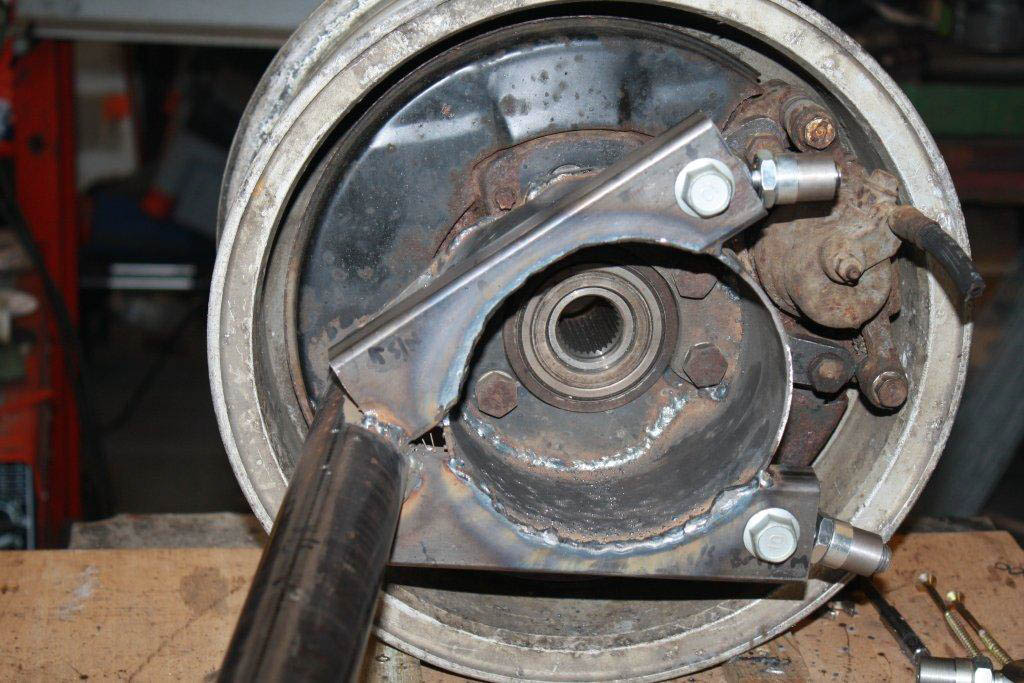
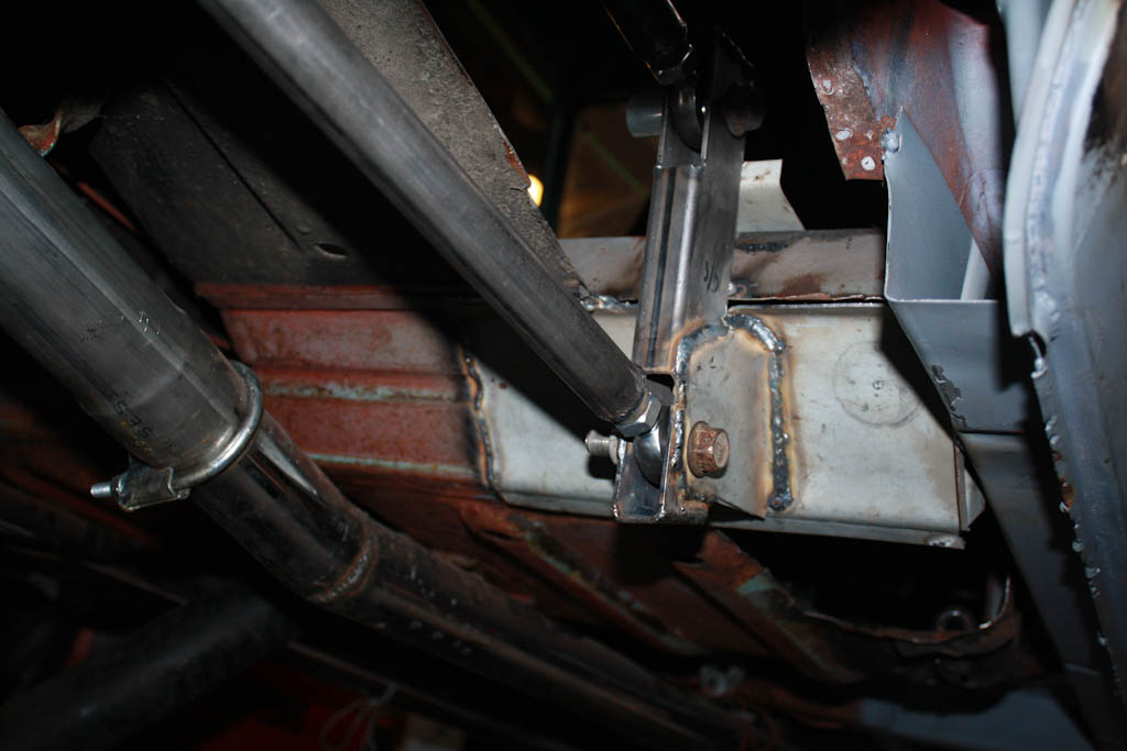
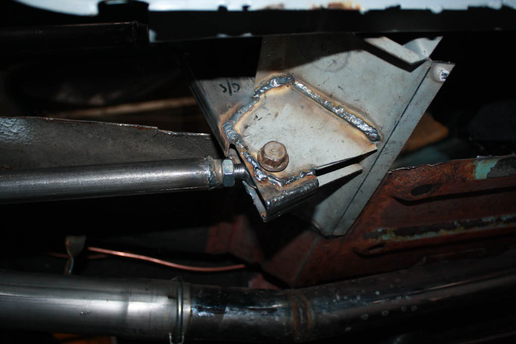
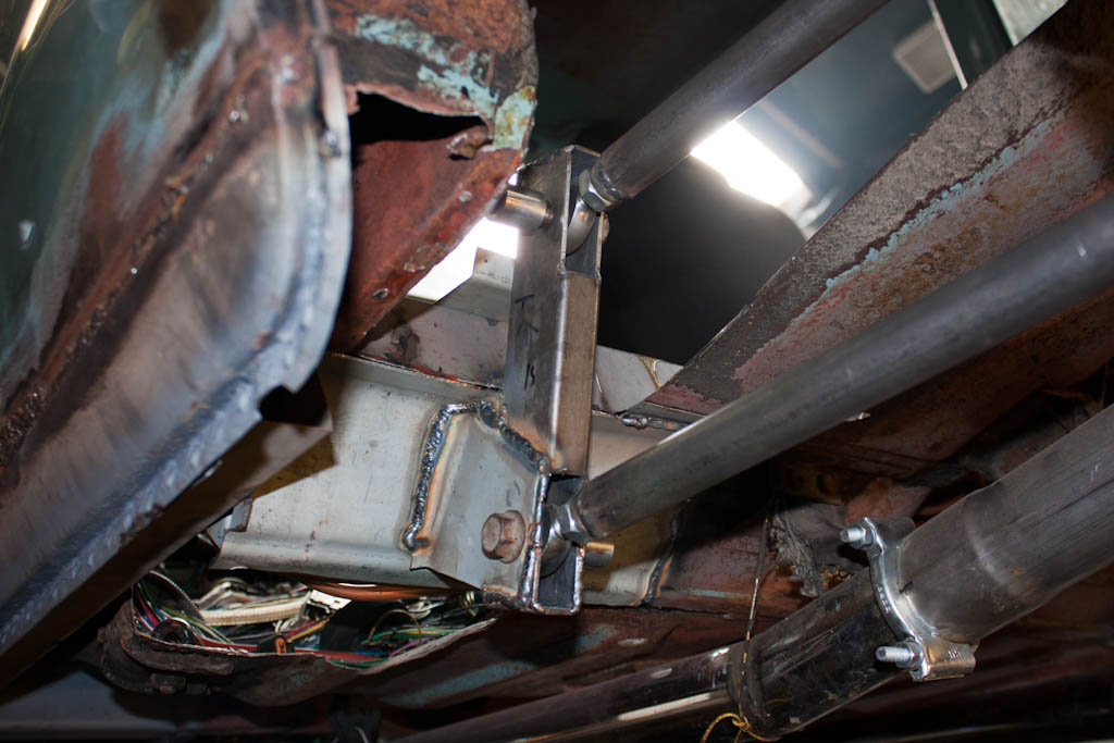
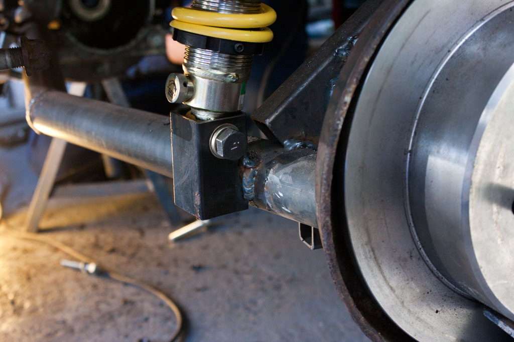
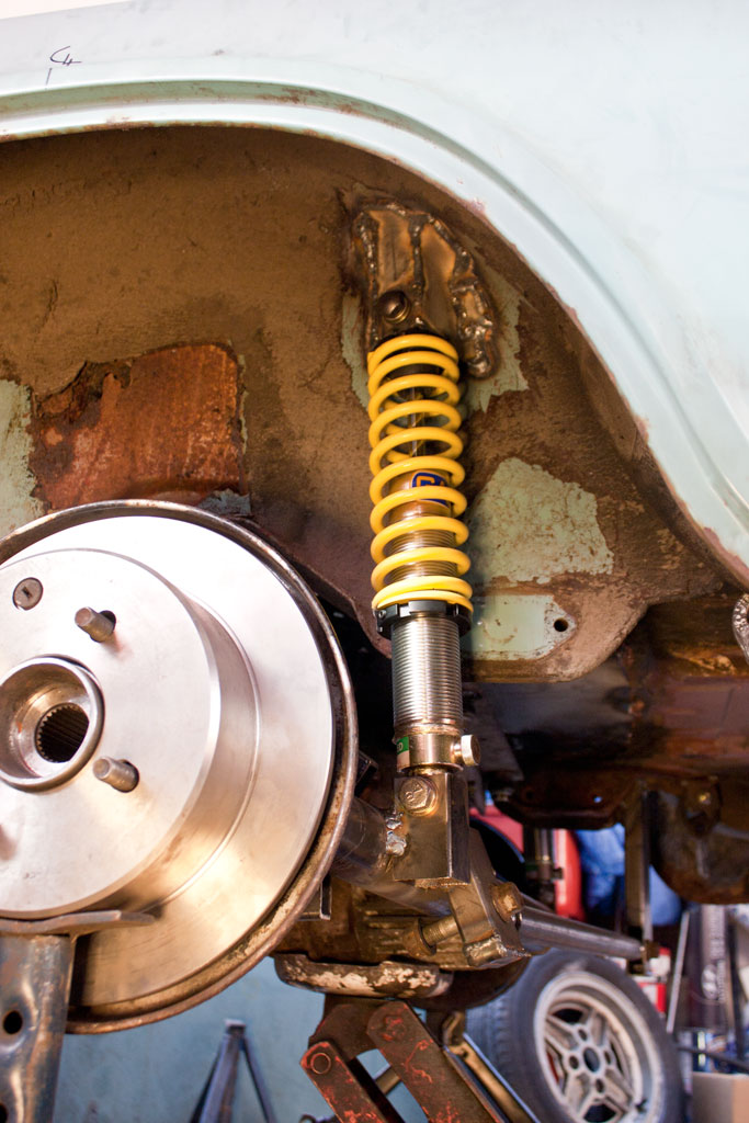
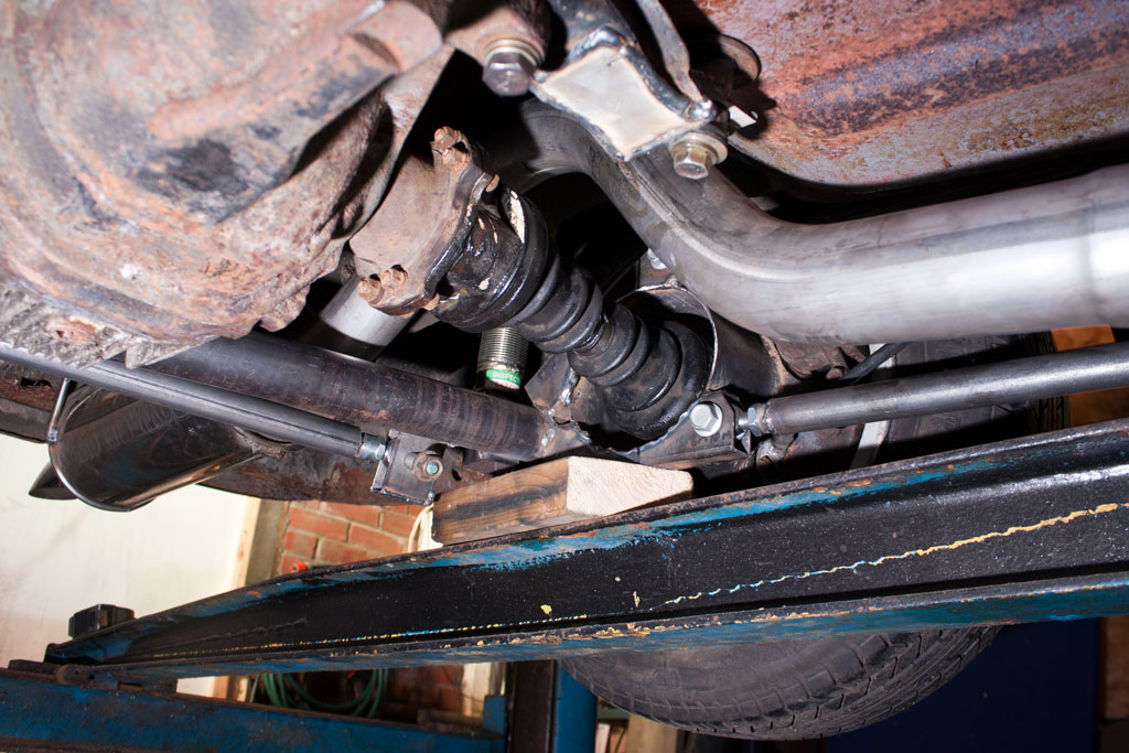
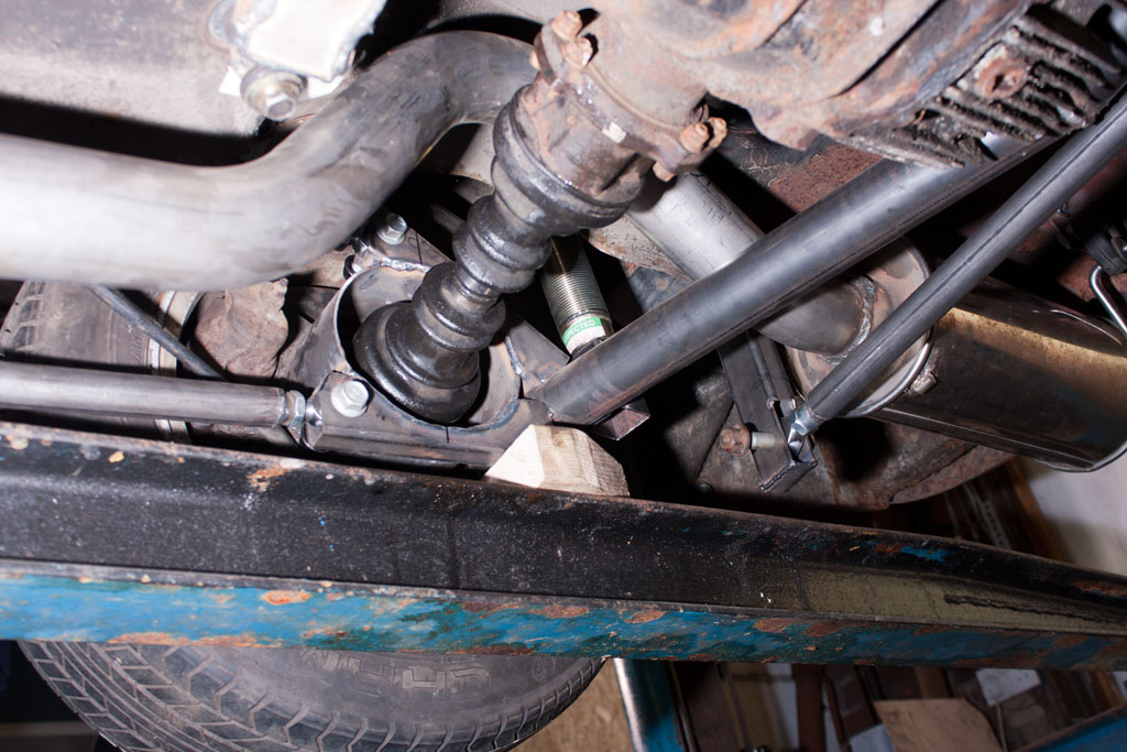
Having worked out the rough ride height with our temporary bracketry and solid bar, I ordered some adjustable shocks and springs, and we re-did the lower mount, and reinforced the top mount. The lower mount will have some additional bracing and welding completed the next time the axle is removed from the car and we can get to it all more easily.

Upper spring mount Lower spring mount Spring

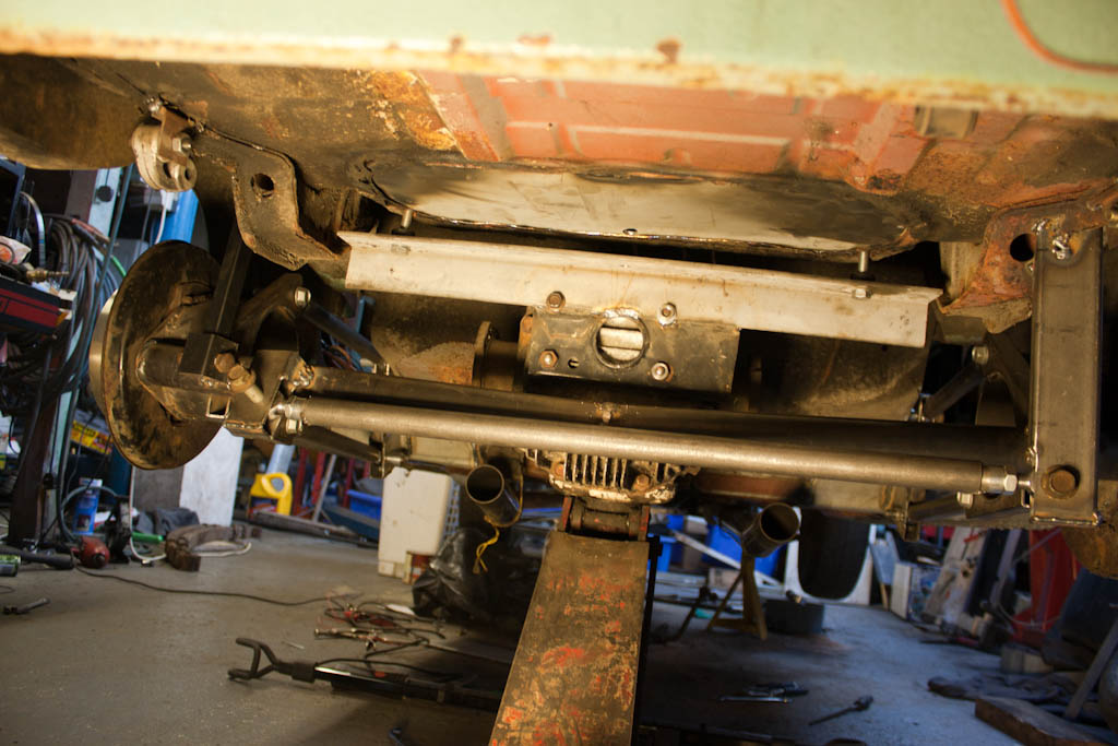
With the de-dion now moving up and down like it should, we need to get some drive to the wheels.

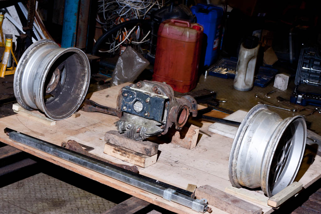
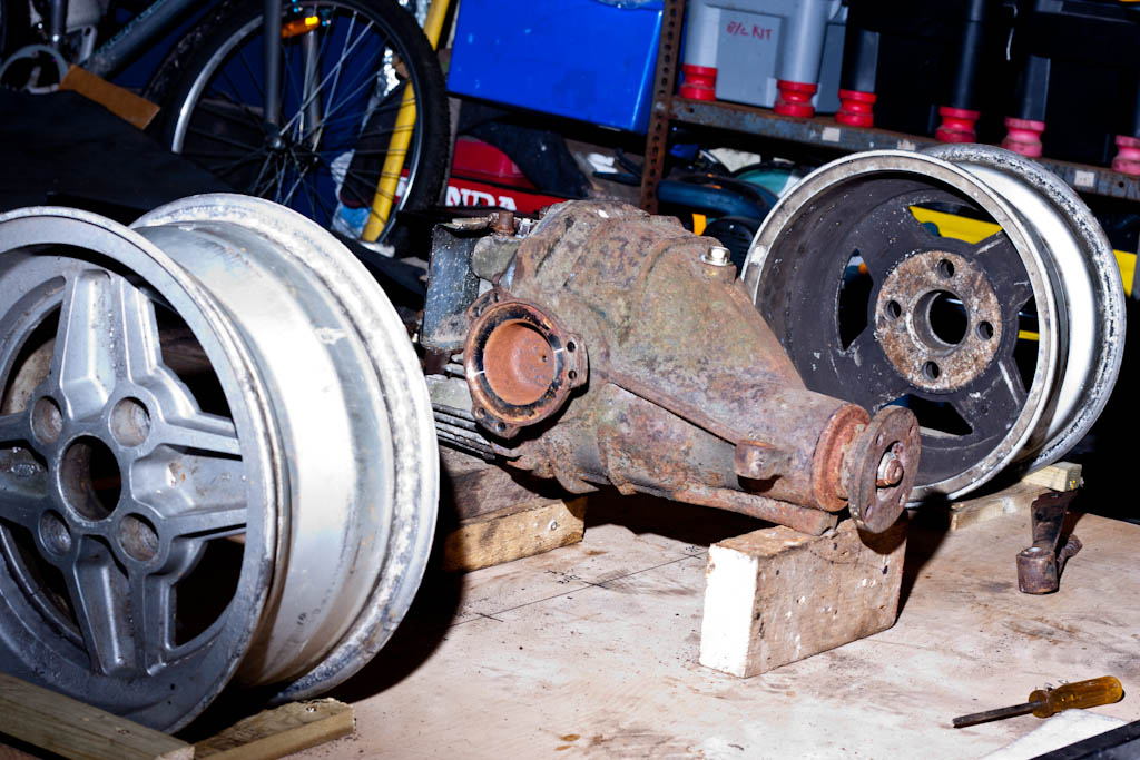
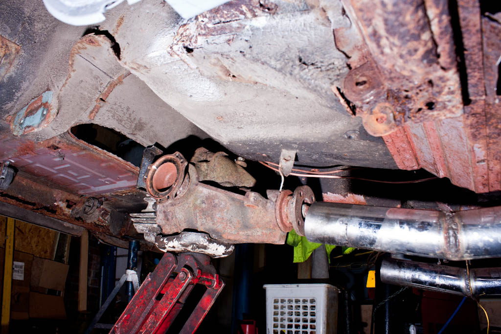
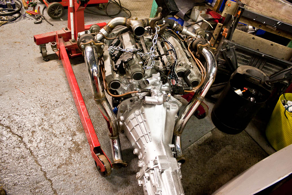
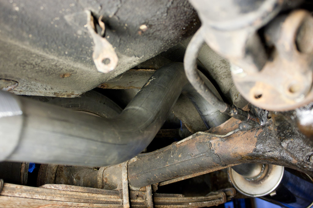
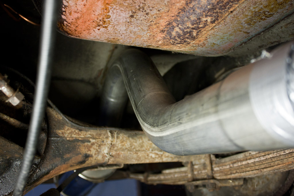
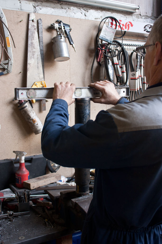
The Nissan diff is about 50mm longer than the Anglia diff, so the Nissan propshaft, which bolted straight up to the Anglia diff, is now 50mm too long to bolt up to the Nissan diff.

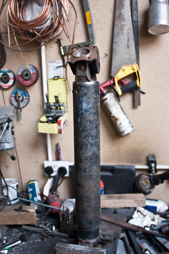
Being a two piece propshaft, we pulled the rear part off, and set about removing 50mm from the length. By clamping it in the vice and utilising a spirit level, we were able to get a clean cut to reposition as necessary.

Propshaft preparation Propshaft preparation

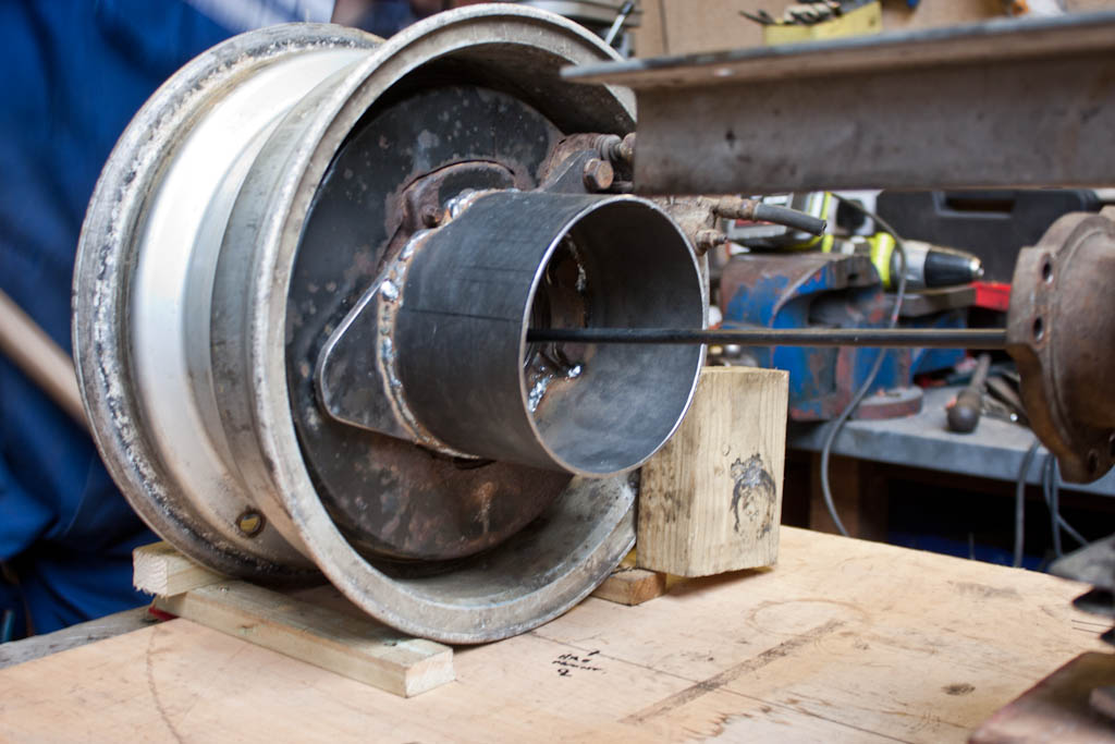
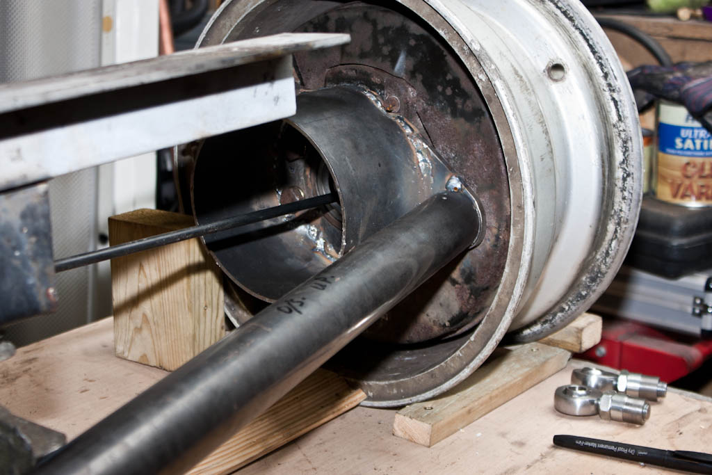
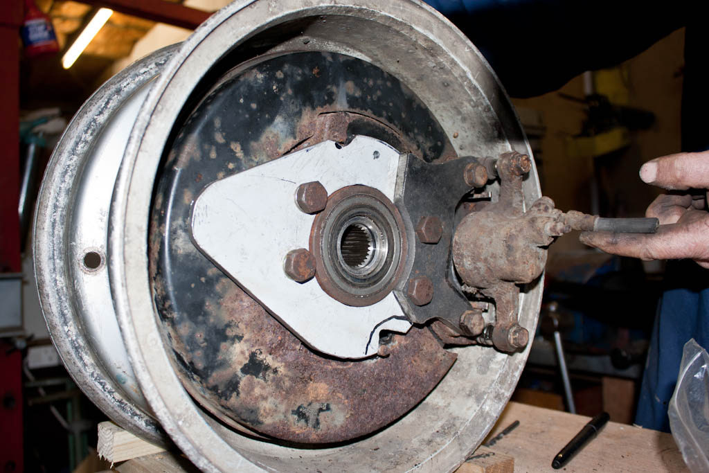
With the propshaft cut to length, next to tackle is the driveshafts. The Anglia is a lot narrower than the Nissan, so a touch more than 50mm needs to be removed from the overall width.

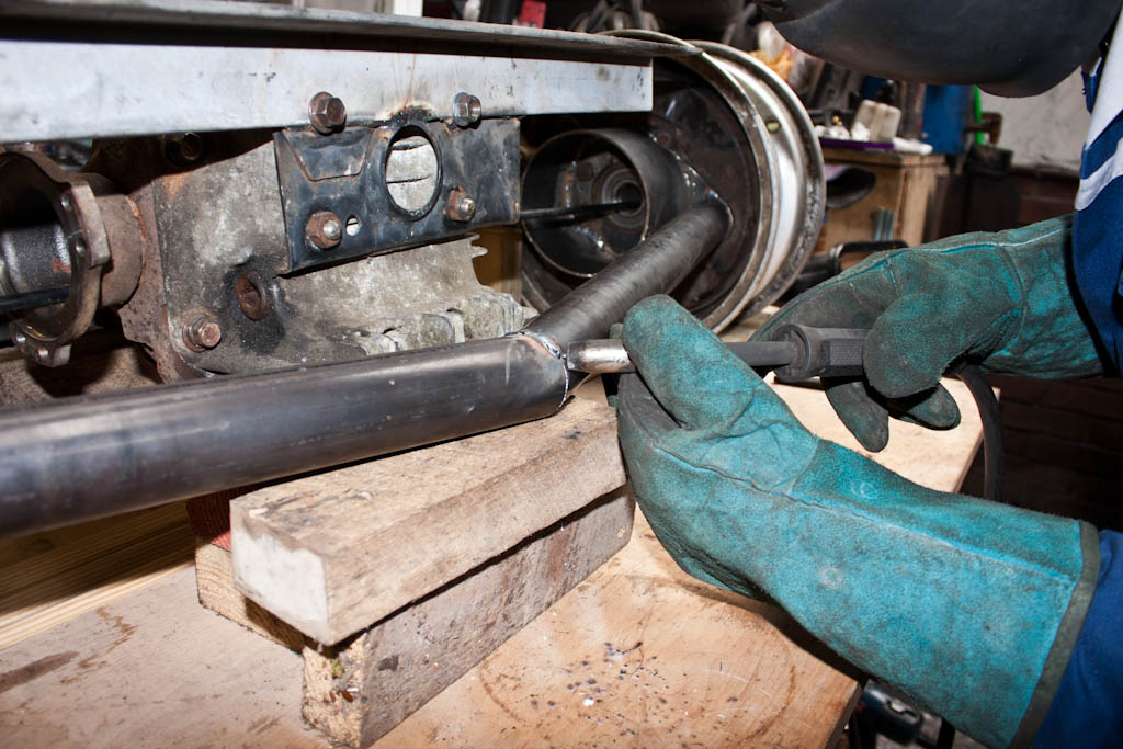
We cut the driveshaft down, and with the use of a lathe and an angle grinder, we V’d the ends to provide a large surface area to weld the two ends back together.

Driveshaft preparation

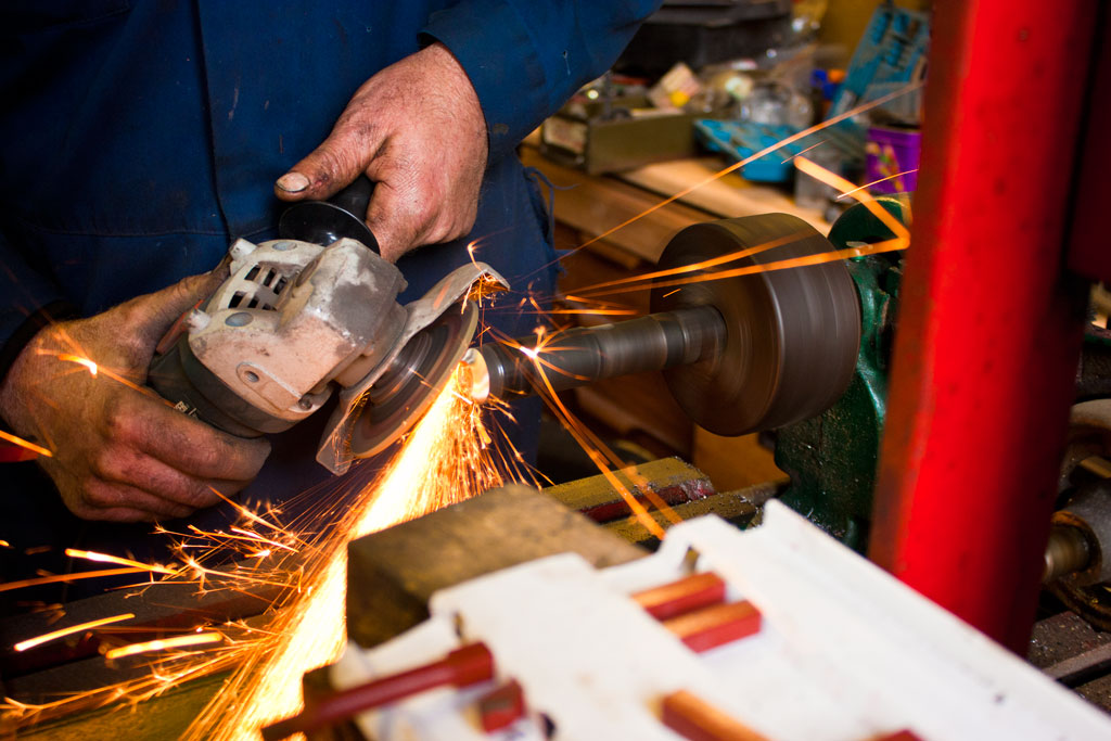
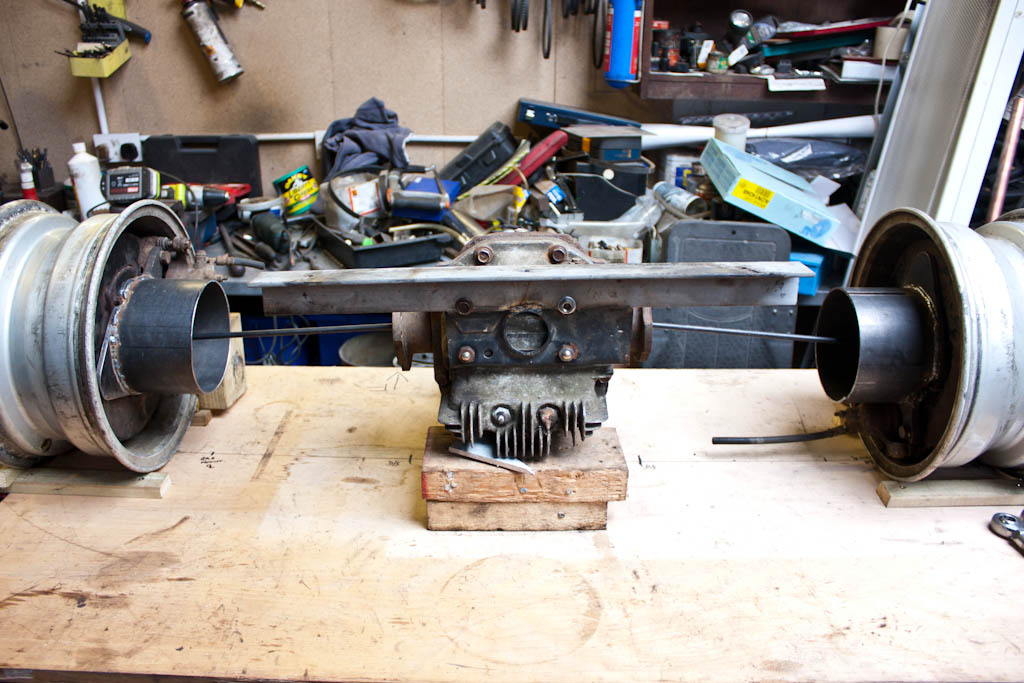
Once welded together, the driveshafts were checked for straightness on the lathe, and the boots were refitted, albeit much closer than previously, and the new driveshafts are attached to the car.

Nearside driveshaft Offside driveshaft

The propshaft and driveshaft modifications done here may not be the final parts used on the car. What they will do, however, is allow me to put something together, which will be at least enough to move the vehicle under its own power, and prove the concept. They may stay on the car, they may fail spectacularly the first time any serious power is applied to them – if they work, brilliant, if they don’t, all I’ve lost is a couple of hours of time, and I’ll get some made up elsewhere.

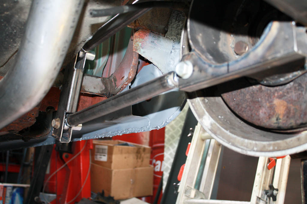
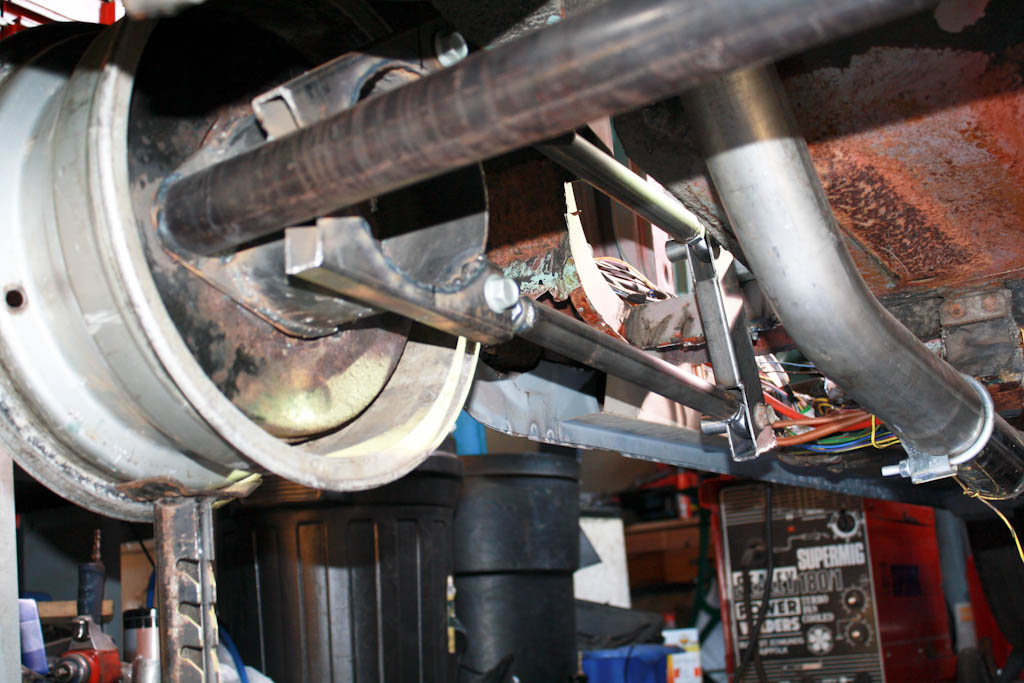
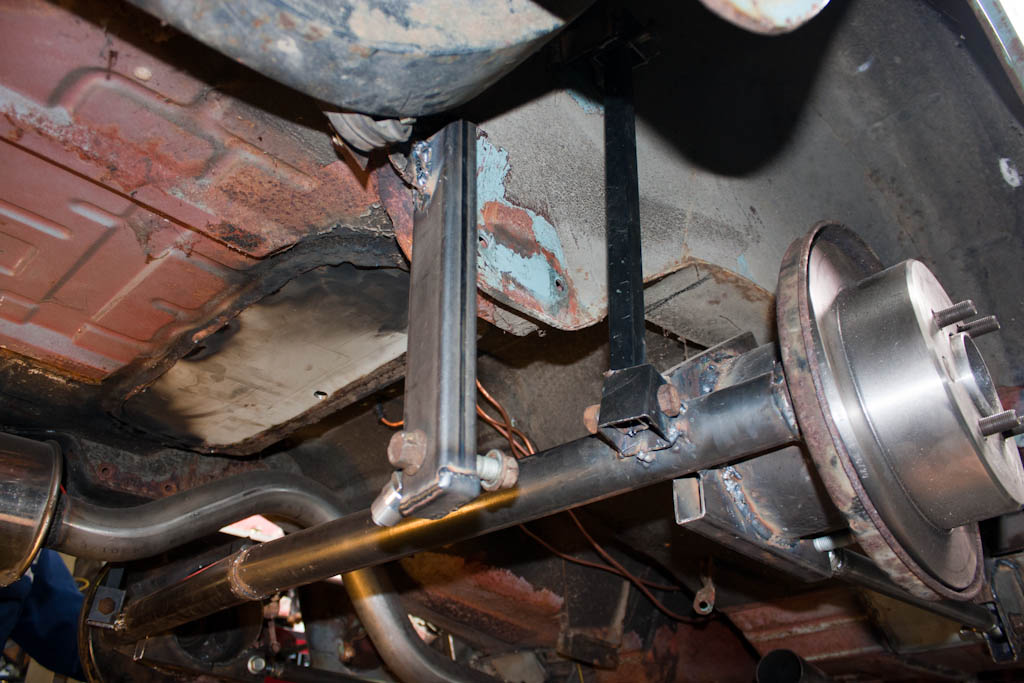
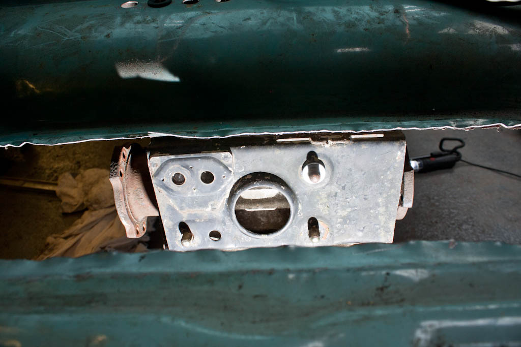
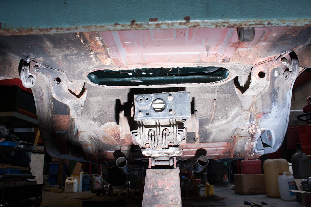
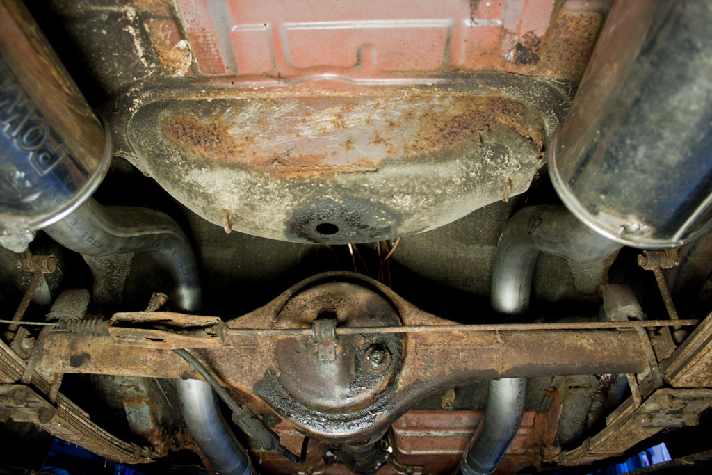
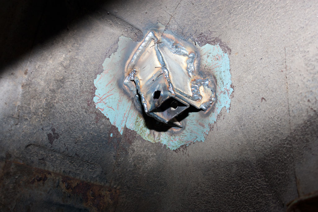
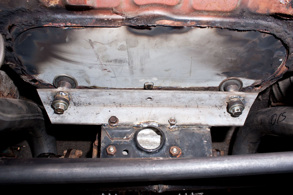
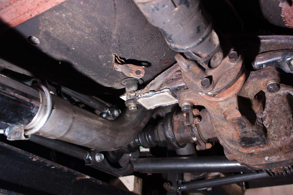
A couple of shots of the diff mountings now. These are rubber bushes within a length of tube, with a long bolt going through into the body. Should absorb some of the vibrations/noise coming from the diff…

Rear diff mount Front diff mount Front diff mount

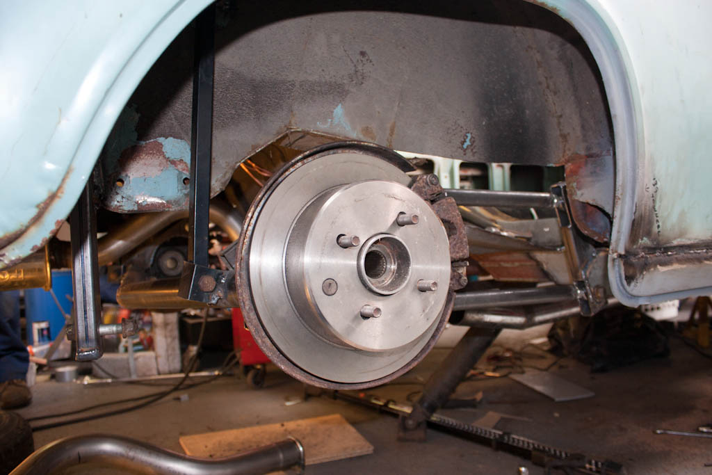
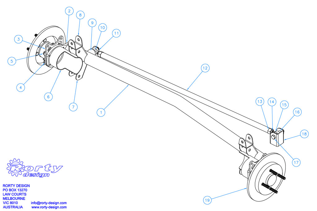
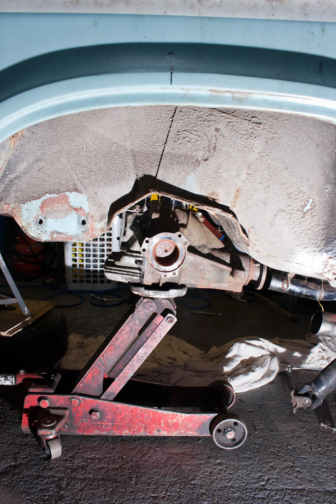
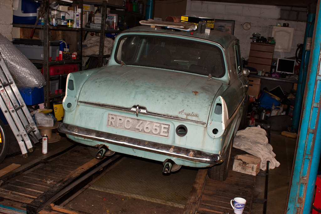
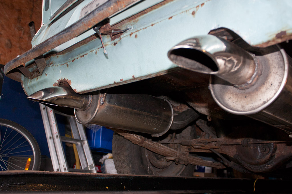
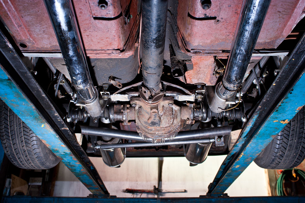
And finally, the completed article. One completely home-made, custom rear axle, to my exact specifications, and should be strong enough to take whatever power the engine can throw at it.

Completed rear axle

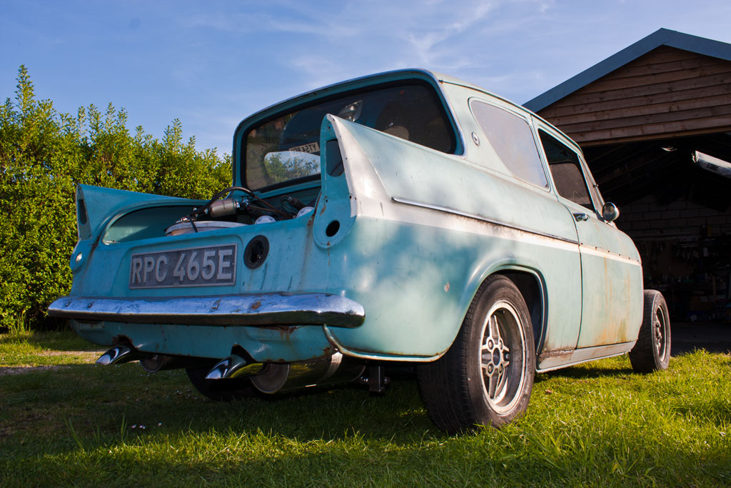
We then couldn’t resist driving it outside for its first little photoshoot outside of the confines of the garage, and to enjoy the surprisingly good weather.

IMG_4824 IMG_4826 IMG_4829

Rear axle: Part 2

Next up on the axle, is the trailing arms. There will be 2 trailing arms on each side, which will prevent the axle from twisting under braking or acceleration.

First up, is to fabricate the mounts on the axle. Utilising some heavy box section, a mount is added to the top and bottom on each side, and fitted with heavy duty M14 rose joints.

IMG_4444 IMG_4440 IMG_4443 IMG_4441 IMG_4442

With the axle end done and offered up to the car, the body end of the trailing arms take shape. The original rotten spring hangers are removed, and another bit of heavy box section is tacked into place, as well as the trailing arms fabricated at the correct length. The trailing arms are made equal in length, and have one left-handed and one right-handed thread rose joint attached – this will allow infinitely fine adjustment to the positioning of the axle within the wheel arch without having to remove it from the car.

IMG_4450 IMG_4451

Additional bracing begins being added to the mounts and the floor/box section. There is still more to be finished.

IMG_4452 IMG_4453 IMG_4760

In order to set the ride height and calculate length of shocks/springs needed, a temporary solution is tacked into place – a length of box section and couple of temporary brackets.

IMG_4758 IMG_4761

The trailing arms will prevent the axle from moving forwards/backwards, but will not prevent it from moving left/right. To prevent this movement, a panhard bar is added. This attaches to the axle on one side, and to the body on the other.

A heavy duty bracket is fabricated and attached to the floor – this wraps around the chassis rail for additional strength.

IMG_4763

The panhard, like the trailing arms, is fitted with a left-hand and a right-hand threaded heavy duty rose joint, which will allow fine adjustment of the left/right position of the axle without removing anything from the car.

IMG_4767 IMG_4769

The diff was also lifted back into the rough location, a length of angle has been added to the mount to move the load closer to the edge of the boot floor, closer to the chassis rails where there is more strength.

Finally – a wheel with tyre (currently 185/60/13) is fitted to see what it would look like.

IMG_4756

Classic Ford

I’ve just had something drop through my door…

Classic Ford - June 2013

A couple of months ago, I had a couple of guys from Classic Ford come and visit for the day, and they’ve written up an article for the Grafters section in Classic Ford.

So – grab yourself a copy of the June 2013 edition of Classic Ford and check out page 8.

Rear axle

Work this time continues on from the work done in the last update – namely the fabrication of a completely custom rear axle.

Having marked out and cut out the bits to mount the bearing units and calipers for the near side, we moved onto doing the same for the offside. After getting everything lined up and fitted to the wheels, it came apart, the paint removed from all bits, and the two parts previously seen were welded together.

After that, the hub bucket (#6) was measure, cut and welded, and it was all reassembled and affixed back to the wheels.

We had also added more to the diff mount, a large piece of heavy-gauge angle section, which will help to spread the load from the diff across a larger section of the body – this is wide enough to be almost touching the chassis rails on either side.

Rear axle Rear axle

We then measured and cut for the main de-dion tube, and began to tack together. We had to be very careful here to get the alignment spot on – any toe-in or toe-out and it will scrub tyres.

Rear axle Rear axle

There is still additional bracing to affix between the de-dion tube and the hub buckets, which will also perform the task of trailing arm mounts.

Rear axle and suspension – the beginning

This may cause some heated discussion on some forums – the topic of rear axle and suspension.

Some will argue that the standard rear axle will be good enough for more power. My dad’s experience says otherwise – in the early 70’s he was breaking diffs with just a 1500GT engine and some aggressive starts – but those were the days when Anglias were easily found in scrap yards, and a diff could be broken on a Friday night, and a replacement sourced and fitted by lunchtime on Saturday.

However, this is 2013, and parts for a Ford Anglia aren’t as easy to come by now.

Therefore – I have decided that I do not want to use any parts of the original rear axle.

I am absolutely not putting wider arches on it, so a wider axle is also out of the question, which means something custom made.

I have a perfectly good diff from the 200SX, which I know will take the ~300ft-lb of torque from the engine, as well as the rear hub units, so instead, I shall be making my own rear axle.

This will allow me to have it the exact width I need, using a diff that I know is good.

I had a long debate with my dad regarding what to do about rear suspension (since, in fact, when I purchased the 200SX), and we debated the original axle (not strong enough), and making either 1) a new live axle, 2) a de-dion tube or 3) fully independent

After discussion of the advantages and disadvantages of each, we decided on a de-dion tube setup. The wheels are linked together, much like a live axle, but instead of the diff being part of this, it is mounted to the floor, with a pair of driveshafts with CV joints to allow travel in the suspension. This will then have a 5-link setup to allow movement and location, with a pair of trailing arms on either side, and a panhard rod to prevent sideways travel of the axle.

rorty-de-dion-design

The above is a design by Rorty Designs, published a number of years back for the LocostBuilders site, based around Sierra parts to replace an Escort live axle on a Lotus-7 style kit car, and has been made by kit-car owners a number of times.

I will not be using Sierra bits (as I don’t have any), so instead will be using this as a general idea of what to do based around the 200SX bits that I do have.

To begin, we set up a board with the wheels and diff, setting the wheels parallel and at the desired width to allow the wheels & tyres to sit within the confines of the standard wheelarches.

Jig for rear suspension Jig for rear suspension

We then began to align the differential to the car, aligning it centrally (to give us equal length driveshafts) – which does mean that the nose will be slightly offset, but the propshaft has enough movement to allow this slight offset.

Diff alignment Diff alignment Diff alignment Diff alignment

With the diff alignment mostly sorted, it was then time to look at the de-dion part of the suspension.

In order to attach the hubs, we need to make up some plates to affix this tube to the bearings. Firstly, was to strip down the 200SX rear hubs, and leave ourselves with the wheel bearing and brake disc assembly. The 265mm discs fit nicely under the 13″ Ford wheels.

200SX rear wheel bearing and disc

We then start with a template, which will be the first piece of the puzzle. This will bolt to the wheel bearing, and will have the de-dion tube attached to (#2 in the above plans).

De-Dion #1 De-Dion #2 De-Dion #3

When this was cleaned up, it was attached to the bearing unit.

De-Dion #4

Caliper mounts (#3 in the above plans) were then made to take the 200SX brakes, putting them in the correct position, giving plenty of clearance within the wheels.

De-Dion #5 De-Dion #6

Next is to make the hub bucket (#6 in the above plans), attach the main de-dion tube (#1), and make up the trailing arm brackets (#7), trailing arms, panhard rod (#12) and the other little brackets to affix.

MAF, MAP?

In ye old days, the amount of air/fuel in the engine was determined by the carburettor.

Modern cars measure how much air is coming into the engine in a number of ways, and the Engine Control Unit uses this value to determine how long to open the Injector to add the right amount of fuel.

The two ways of measuring how much air is going into the engine is by using a Mass Airflow Sensor (MAF) or Manifold Absolute Pressure (MAP).

The Mass Airflow Sensor originally used on the Mitsubishi Galant that the engine came from uses the phenomenon of a Kármán Vortex Street – the principle that air flowing around a blunt object comes back together in “pulses” to create vortices – the faster the air is flowing, the more vortices are created in a given time interval. (Other vehicles use different types of MAF, which measure the air in different ways)

This is where we get to the second method for detecting how much air is in the engine – Manifold Absolute Pressure (MAP)

This method uses a pressure sensor in the manifold, and the engine speed to calculate how much air is in the engine.

Each of these methods also make use of an Intake Air Temperature sensor (air is more dense when it’s cold), and a barometric pressure sensor (air is thinner as you go higher) to calculate the amount of air more accurately.

On the original Galant, the MAF is placed very early in the inlet – immediately after the filter, and before the turbos. Given the space constraints of the Anglia compared to the Galant – there is not enough room to locate the filter and MAF and get the air pipework to each of the turbo inlets.

Therefore, some clever soul in New Zealand invented the MAP-ECU. This little magic box of tricks makes use of a MAP sensor and engine RPM, and will emulate the frequency output of the original MAF, so that the standard ECU is still getting the signal it expects.

It can either be programmed from scratch with the correct values, or it can be run in “auto-learn” mode, where you will run the vehicle for a while with the original MAF still connected, and the MAP-ECU will learn what the standard MAF is outputting for the various pressure/RPM cells.

The problem I had with the engine not revving was that the MAP-ECU was not correctly configured for how I had wired it up. The original owner of the MAP-ECU had the RPM signal connected to the wire which had the pulses from all 6 spark plugs (so to get the correct RPM, you divide the number of pulses received by 6) – I had wired it to the signal for just 2 spark plugs – so as the engine revs increased, the MAP-ECU was not moving into the correct cell, and was not telling the standard ECU that there was more air going into the engine. Once I told the MAP-ECU to divide the number of pulses it’s seeing by 2, it was reading the correct RPM.

Cooling down

After managing to get the engine up and running last time, we had a small issue – any touch of the throttle would cause the engine to stall.

We didn’t run the engine much past what was shown in the previous video, as we had no way to cool the engine. So, we spent some time putting together a cooling system, which would allow us to run the engine for longer than a couple of minutes, and perform some troubleshooting.

With some pipework made from some large bore pipe, and a loop of pipe on the heater circuit, we hooked up an old Mini radiator we had sitting around, to be able to get some coolant into it.

We refilled the “petrol tank” with petrol, hooked up the battery again, and I hooked up my laptop to the engine ECU to run EvoScan, and to the MAP-ECU to run the MAP-CAL software.

Upon starting the car, we could see that the RPM within EvoScan was around 700rpm, but it was showing at just 200rpm in MAP-CAL. The MAP-ECU was previously attached to a 6A13TT engine, and in the configuration it had been set to “6 cylinder”. The RPM wiring had obviously been on the signal to the tacho in the dash, rather than how we’ve now wired it – direct into the signal from the ECU to one of the coils. Changing the MAP-ECU configuration to “2 cylinder” then showed the correct RPM – and instantly we were able to rev the car properly.

The MAP-ECU “mimicks” the Kármán Vortex Frequency given out by the standard MAF by utilising RPM, manifold absolute pressure and intake air temperature – with the RPM incorrectly set, it wasn’t moving out of the correct RPM/pressure cell and adjusting the VKF frequency output correctly – this was then not telling the standard ECU that the amount of air had changed (increased), so was not adjusting the fuelling correctly – hence the immediate stalling.

Down to the wiring

In my excitement to post up the video last time, I didn’t get round to adding some additional photos that were taken. So… here they are!

I start this update again with another photo of the engine and gearbox out of the car – this time to finish welding up the exhause downpipes where we couldn’t get to them whilst it was in the car. We also took the opportunity to begin tidying up and re-routing some of the cabling from the engine, as our work last year to route it all through the existing heater hole was beginning to look a little too untidy for my liking.

The engine and gearbox went back into the car, and we put the remaining engine wiring back on, and continued to re-route and tidy, and in the process put all of the engine wiring into waterproof plugs, so that it’s easy to disconnect from the rest of the car.

Once that was done, the engine bay is looking a lot neater without all that wiring on show.

Then onto the daunting task… sorting out the rest of the wiring. We had already removed quite a lot of unneeded wiring last year by removing everything attached to the automatic gearbox ECU, but it still left a large amount, so it was time to try to plug it all together, and work out what went where in the original Galant, so we can begin cutting unneeded bits out.


Now… what goes where again?

Once everything had been laid out and identified, we began to cut out the unneeded bits – AYC wiring, Active Stability Control wiring, ABS wiring, rear doors, heated rear screen, stereo wiring… To do this, we removed all the existing spiral wrap and insulation tape, and began at the endpoints of these systems, separating the wiring into “wanted” and “not wanted”. The “not wanted” bits were chopped out when we reached a connector plug, and then chased from the other side of the plug and removed.

There’s probably still more to come out, but we’d identified a large amount to remove, and we were confident that what we had was sufficient to get to the final end goal of the weekend – which was to start the car! You’ve seen the results of that already!

On a visit to the scrap yard, we spied a nice bit of aluminium pipe which looked like it might have been perfect for the inlet tract – so we quickly knocked together the remainder of the inlet. The straight bit off the Y-piece will be replaced with a water-to-air charge-cooler.

So… what was does the un-needed wiring look like…?

That doesn’t even include any of the automatic transmission etc stuff we removed last year!

And finally… the final bit of original Anglia wiring to be removed, the front-rear loom:

Completely Exhausted

The timing of this update is quite apt, having just received an email from Old Skool Ford forum listing their Favourite Projects, and included in the list is my little project! So, a huge thanks to the staff at OSF for the shout in their mass email!

It starts with a quick trip to collect some shiny bits for a good price, and to try to squeeze it into the back of a Fiesta because I forgot to pick up the hacksaw I placed in the hallway the previous night before leaving – which in itself was quite a feat of engineering! 😉

Having successfully collected the exhaust, which was previously fitted to a VR-4, the backboxes were chopped from the pipework, and lifted into place to measure up and see what it would look like with the 5″ exit… the answer… a little stupid, especially on such a small car! No pic, unfortunately!

So, the outlets were also chopped off, and the boxes were lifted into place to measure up for the other pipework.

The exhaust bits already on the car were marked, cut, and adjusted to follow the line of the floor better, and in preperation for adding of the next parts.

I also purchased some 2.5″ stainless over-axle exhaust sections, as they were available cheaper than making our own sections or buying various angled bits and welding together ourselves. These were fitted to the backboxes, and some brackets were made and welded to the chassis to support via some new exhaust rubbers.

Moving onto tailpipes, and we again utilised some offcuts from a section that has provided other parts of the exhaust, which was the enclosed ends of the bumper bar which forms the turbo elbows. The rear valance was roughly chopped to accomodate the second tailpipe, and they were fitted.

The enclosed bits were removed to give a pair of downdraught tailpipes – and hopefully nicely subtle!