Propped up, shafted and blown twice

This will be the final update from the week of work on the Anglia, so we finished the week by finishing up a couple of bits that had been partly started.

First off, the propshaft. The Nissan propshaft was the perfect length to mate up the gearbox and the standard Anglia rear axle, but it wasn’t supported at it’s centre joint, well, other than by a small piece of electrical wire!

A more permanent solution was required, so a couple of small bits of box section, with a bolt welded in place, and then welded to the inside of the transmission tunnel should do the trick:

Moving into the car, and the steering shaft needed supporting between two of the joints. A simple bracket, and that was done:

I also managed to pick up another rear turbo and manifold, as well as a manual throttle body, which doesn’t have the Traction Control stuff on the side of it. We bolted the turbos into place, and we could now see how the space was being used up quite quickly!

During the making of the pipework for the turbos, we decided to drag the fibreglass flip front out, and put it on the car, to ensure we’d have the required clearance under the bonnet for the myriad of pipework that will be required. So, here’s a couple of photos of it looking somewhat more like a normal Ford Anglia.

Unfortunately the current schedule of visits every 4 weeks means that the next scheduled visit falls on the weekend Christmas, so no work will get done then! So, you’ll have to tune in at the end of January for the next instalment!

Scrapheap Challenge

With one downpipe completed, it’s time to move the turbo back to the other side, and make another.

So, one flange marked and hole enlarged to suit and welded together:

And fitted in place:

Once that was done, we moved efforts onto the brake/clutch, which we’d started a couple of days ago. We had sitting around brake and clutch master cylinders from a Honda Prelude, so began trying to make them fit. However, the brake master cylinder was too big, and we couldn’t get a smooth enough action.

We had to take a trip to the scrapyard to get rid of some old junk, so we did our “Scrapheap Challenge” bit and looked around, and came back with a brake master cylinder from a 2001 Fiat Punto, which wasn’t as long, and, we made up a bracket to hold them in place. Also from the Punto came the reservoir, which is shared between brake and clutch – which means less things to fit into the engine bay on the Anglia!

Have we blown it?

The biggest issue we’ve been worrying about is how we’re going to fit the turbos. They won’t fit in their standard locations. We decided to bite the bullet, and try to come up with a solution.

We took a trip to our local engineering firm again with a rear turbo, and a sheet of steel, and came back with a set of flanges:

One of the flanges bolted to the rear manifold:

A small bit of nice thick pipe (Mitsubishi L200 rear bumper bar):

And one turbo in place:

Now to rinse and repeat for the other side:

Next step is the downpipes, so out with a nice bit of stainless steel rear bumper bar, marked out, cut and welded into place:

Once we’d marked up where the downpipe would fit, we extended the hole in the flange to incorporate the wastegate before welding it all together.

Well… that wasn’t as bad as we expected – only a day to mount two turbos and one exhaust downpipe. So, yes, we have blown it now! 😉

It’s under control

I thought it about time some control was brought to this project!

So, first off, how about some engine control, with the beginning of some of the multitude of wiring? I’m stripping out wiring for any systems that were present on the Galant, and won’t be on the Anglia.

So, that means removing: ABS, ASC, AYC, SRS, TCL and Automatic Gearbox ECU.

After starting with the engine and ECU looms, and re-routing, we’re currently set up as such:

Before going too much further with the wiring under the dash, a small amount of adjustment is required to fit the water manifold to the back of the engine. Firstly we had to trim down the top of the gearbox casing.

And in order to run the coolant hoses to the front, a small amount from the bulkhead.

Next on the agenda is some way of telling the car where to go, so… one Mitsubishi steering column and wheel 🙂

With the ability to steer, I think the ability to move and stop might be the next logical step.

The clutch/brake pedals are an old set of dual controls which were removed from another car, and the accelerator is from the 200SX.

Now that the steering and pedals are done, the bit of floor that had been hacked about to previously fit the Escort steering column was then replaced with a nice fresh bit of steel.

Start you bastard!

Upon my travels of the internet I found this – I know it’s old, but the old ones are often the funniest!

I left you last time with a marriage of an engine and a gearbox mated together – which even I wasn’t sure would have worked until we managed it!

The next issue to tackle was that of actually starting the car. Our adapter plates were taken back to our local engineer with some more rough scribbles, and they were returned with some new holes.

A minor tweak, and the starter bolted up to the engine, and in line with the flywheel – and then, for the moment of truth… would it work?

Success! Next, to get the starter fitted to the gearbox. A small bit of cutting later…

As you can hopefully see, the starter is rather close to the crossmember – and the gearbox is currently lifted higher than it will usually sit – which means that the starter will be trying to sit in the crossmember, so some modifications are required.

So, we cut away a section, and reinforced where we’d removed, as well as reinforcing where we’d cut away the original engine mounts, as we’d not be needing them.

The eagle-eyed among you may have noticed a couple of blocks of wood between the front crossmember and the sump of the engine in the final picture of my last update – this is what was supporting the engine in the right position. I don’t think that would have been a long-term solution, so a proper engine mount is required.

Upon my browsing of forums as I usually do of an evening, I happened upon someone selling a brand new engine mount from a Honda Integra DC2 – which looked like it might fit the bill. I promptly purchased it, and work began on making it fit. A large chunk of the original engine mount was removed, and a wonderful looking mounting bracket was created.

In order to support this, we’d need some quite hefty bracing, so the remainder of the bodywork was removed, and some additional box section was grafted into place.

The engine was then lifted back into position, and the front engine mount was affixed securely to a beefy bit of box section, and the engine suspended from it, and the gearbox crossmember.

With the front and rear mounts sorted, something was needed to stop the roll of the engine. Using the mount from the Honda Integra gave me another idea. I often see Hondas with “engine torque dampers” to reduce the engine movement from their huge torque outputs *snigger* – these are small units which don’t take up much room… perfect for this case.

So, a couple were purchased, and mounts made to prevent the roll on the engine.

There we are – that should damp more torque than the 2 Hondas they were no doubt previously destined for!

And finally – another treat, a video which is “out of order” of the text above, but I couldn’t leave this update without putting it in!

A marriage of unsuspecting items

It’s been a while since the last update, however it’s not been that I’ve not been doing anything…

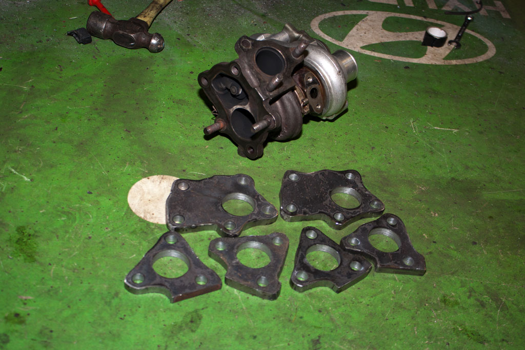
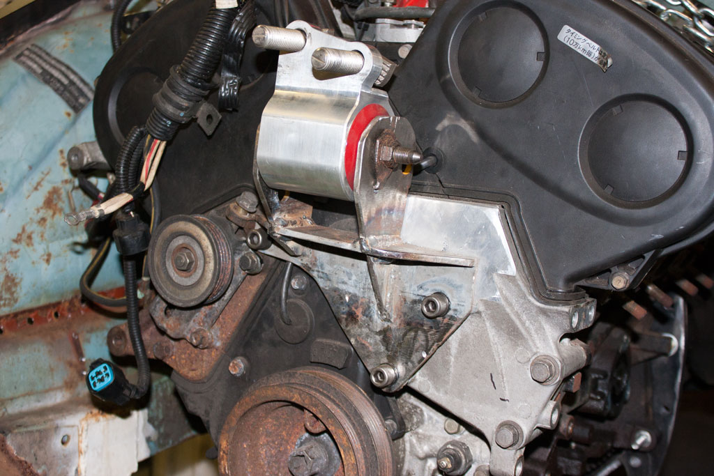
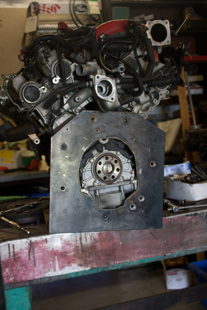
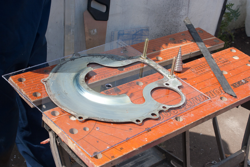
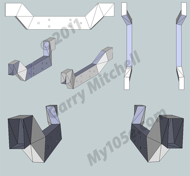
We took our perspex templates to a local engineering firm, and asked for exact copies but in something a bit more suitable for the job – 8mm steel. After leaving it with them for a few weeks, we received back some goodies!

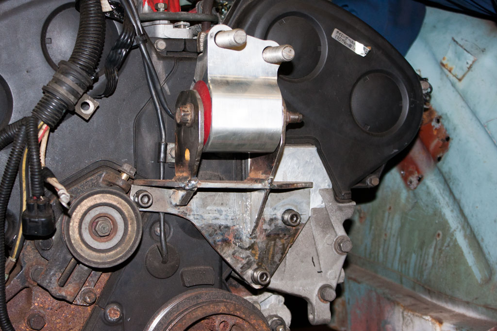
And the equivalent was bolted to the gearbox – an interesting tidbit, the bolts we wanted to use are M10x1.25 thread countersunk approx 2″ long, so we went to a local fastener supplier, to be told “no one makes them” – a couple of days later my dad was removing a Hyundai gearbox and he removed something that apparantly doesn’t exist… so we put in an order at the parts desk and within a few days had enough to bolt up the engine and the gearbox adapter plates!!

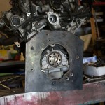
I picked up a VR-4 flywheel (the engine came from an automatic), but with the 8mm adapter plate, the back edge of the flywheel was a bit too close for comfort, so we had made up a 5mm spacer to bring the flywheel away from the block.

We then hit a snag – the VR-4 flywheel is 240mm (and has a pull-type clutch), and the 200SX S13 clutch is 225mm. A quick post on SXOC and I was informed that an S14 clutch is 240mm, but won’t fit inside the S13 bellhousing. So a VR-4 clutch wouldn’t work because it’s the wrong type, and an S14 clutch wouldn’t work because it won’t fit.

The n/a Galant and the FTO both share the 6A1 series engine, and both have 225mm clutch. So I borrowed an FTO flywheel and clutch, removed the friction plate and put in place the 200SX friction plate.

This then allowed the engine to transfer drive through as far as the gearbox input shaft.

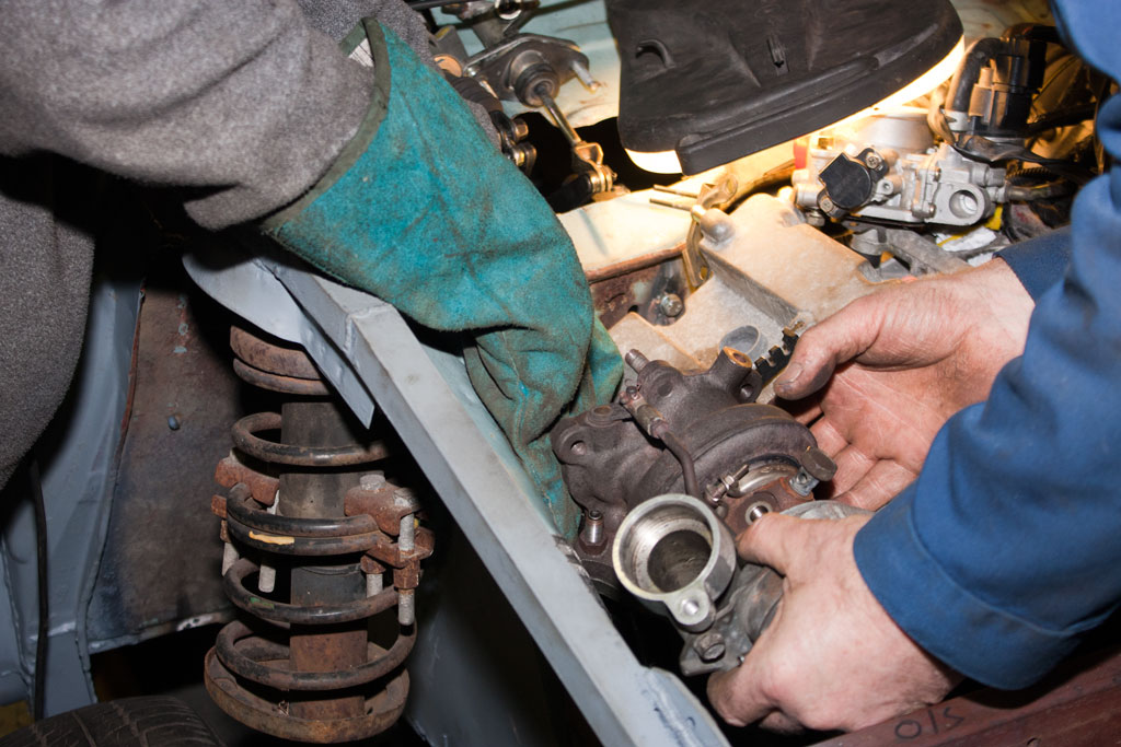
In a RWD box, the input shaft is supported in the end of the crank, but in a FWD or transverse gearbox (as in the VR-4) has the input shaft supported both ends within the gearbox itself, so there are no spigot bushes, and therefore no way to mount one into the VR-4 engine. So, again to our local engineering firm, who turned us up a spigot adapter to fit the end of the crank, and to fit the brass spigot bush from the 200SX.

With all this in place, it was time to try mating the two together.

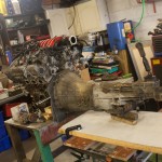
They slotted together *perfectly*!

A ratchet on the end of the crank, and the gearbox in gear, and the output shaft turned – a joyous occasion!

The FTO clutch cover had the fingers further towards the centre than the 200SX clutch, so the standard 200SX release bearing would have not worked. And a Mitsubishi release bearing wouldn’t have fitted over the input shaft.

So, we’ve cannibalised the original 200SX release bearing for it’s casing, and a Mitsubishi Shogun release bearing for the bearing part, and we’ll send that off to have an insert made to hold the Shogun bearing in the 200SX casing.

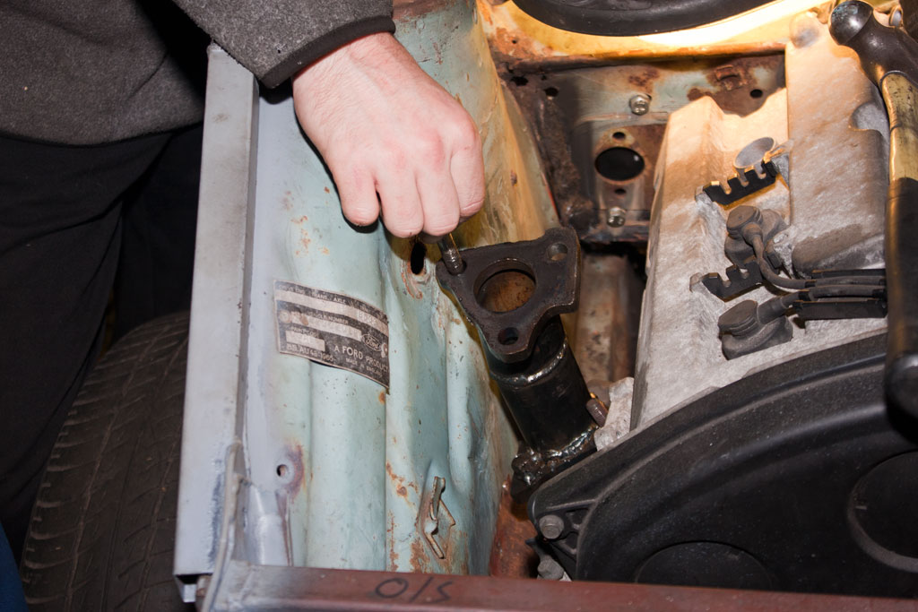
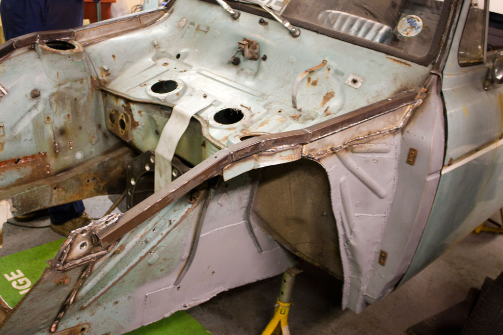
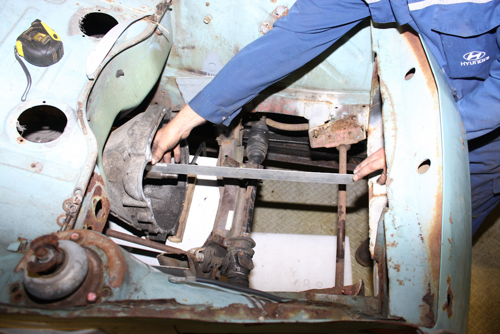
It was then time to put the two units together, in the car. First up was the gearbox.

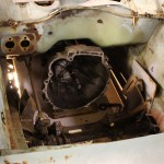
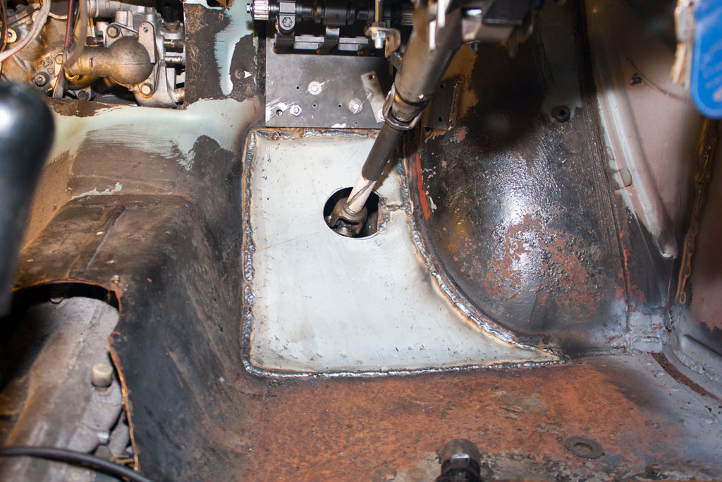
The gearbox slid into position almost perfectly. The tail sits just through the crossmember, and clears the tunnel! We used a nice straight bar to align the input shaft with the crank handle hole on the chassis.

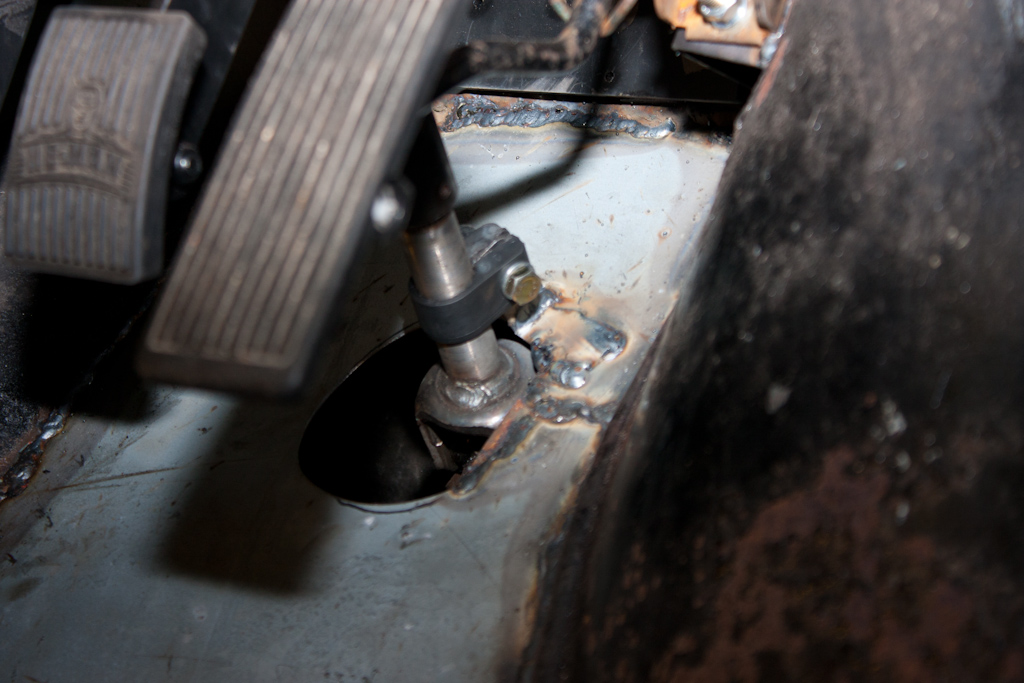
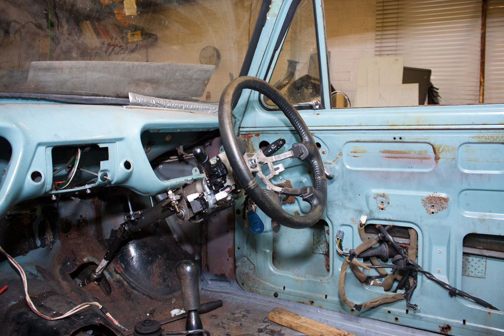
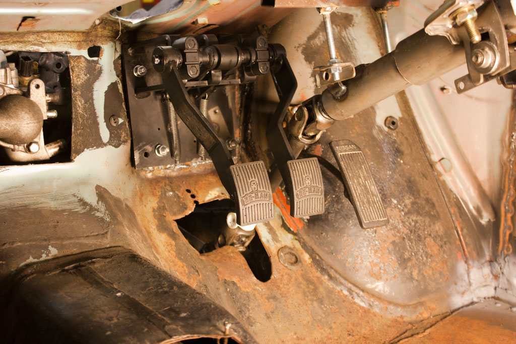
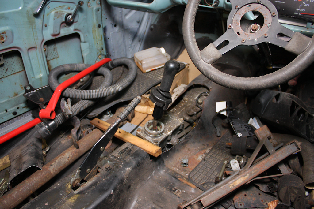
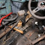
The only bit we needed to trim was for the gear lever to come through – just in front of the handbrake, and almost exactly in line with the steering wheel’s current location!

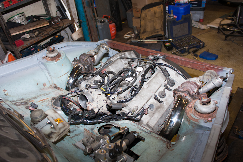
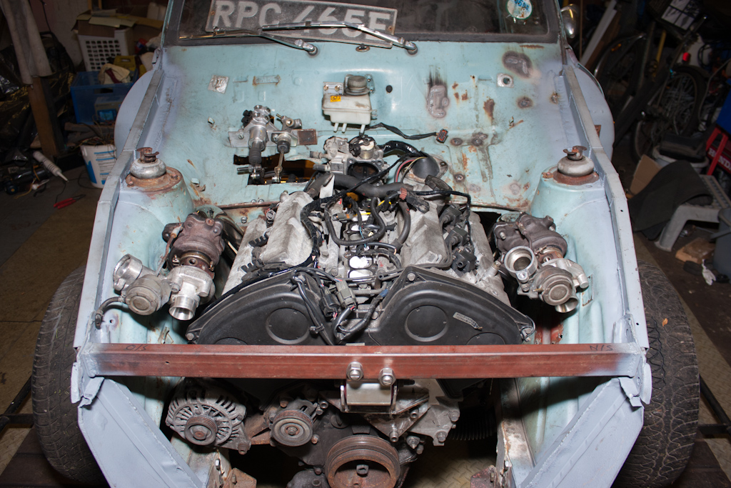
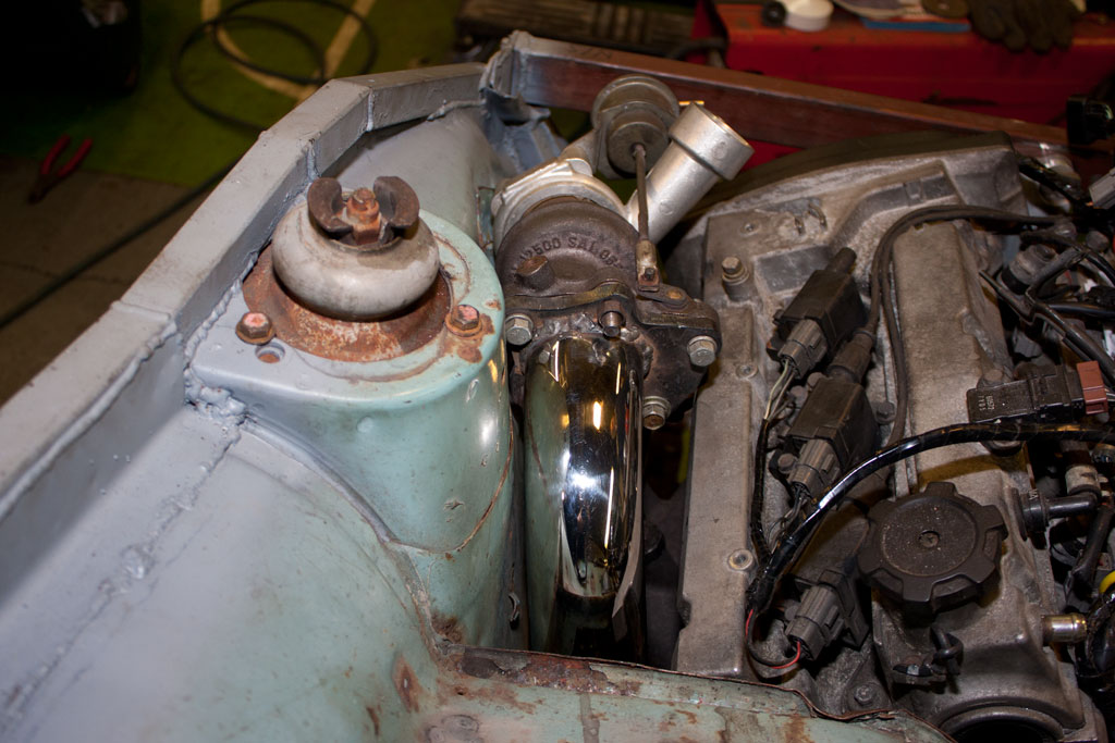
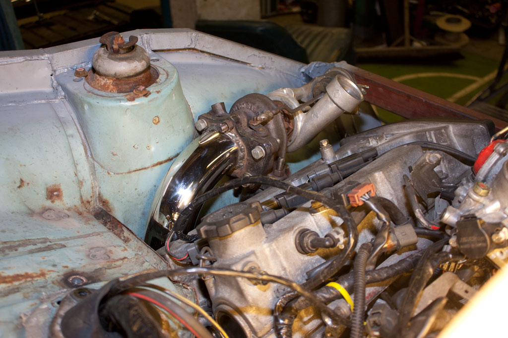
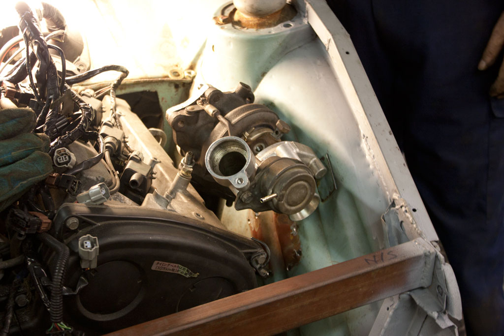
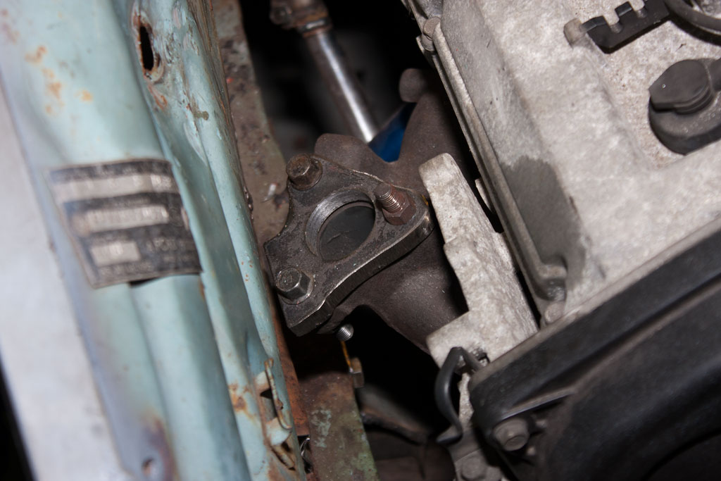
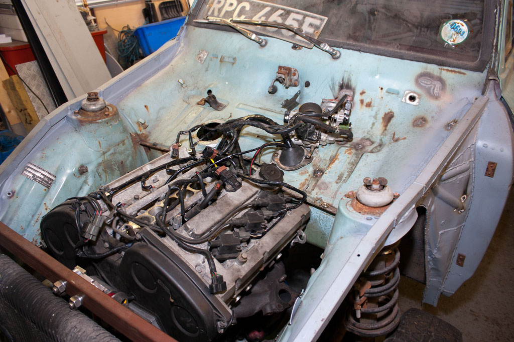
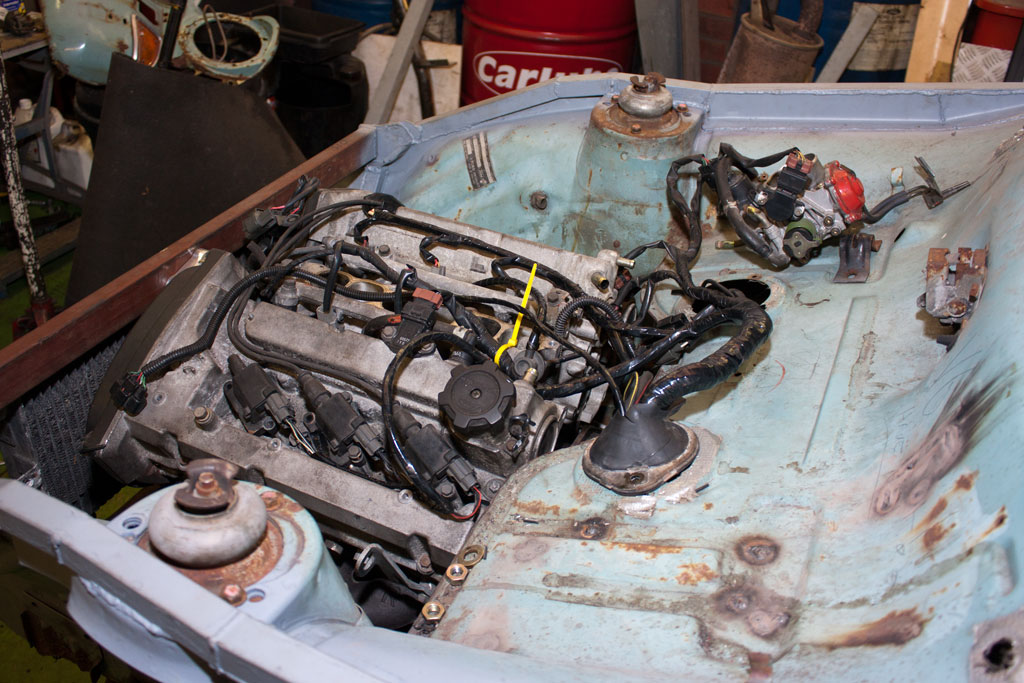
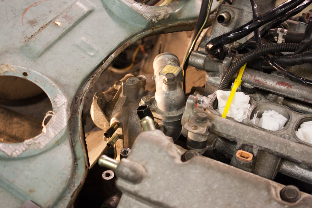
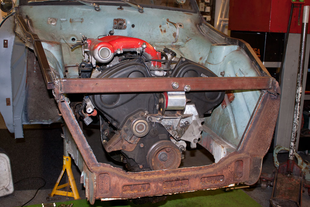
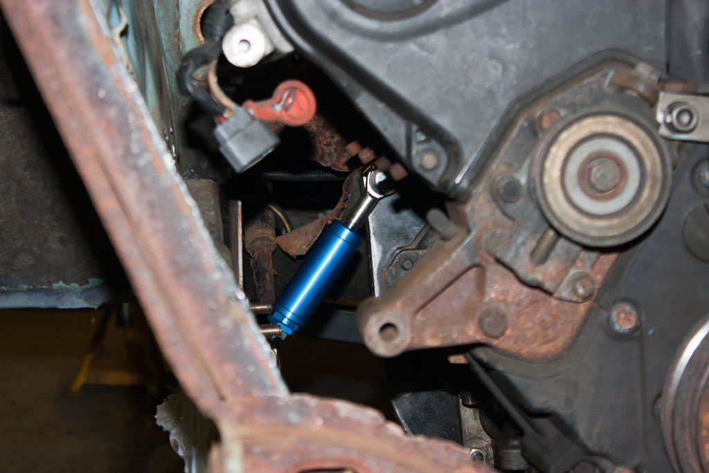
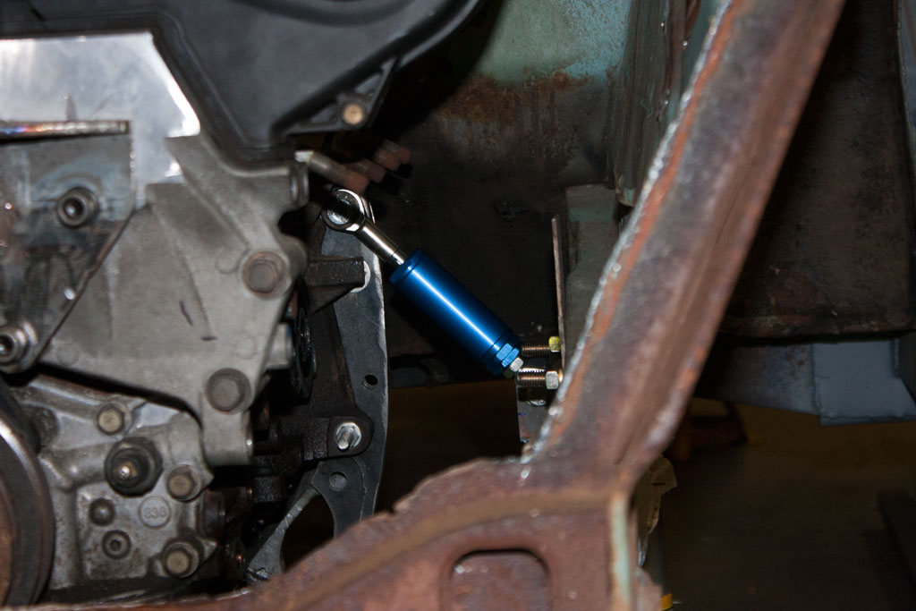
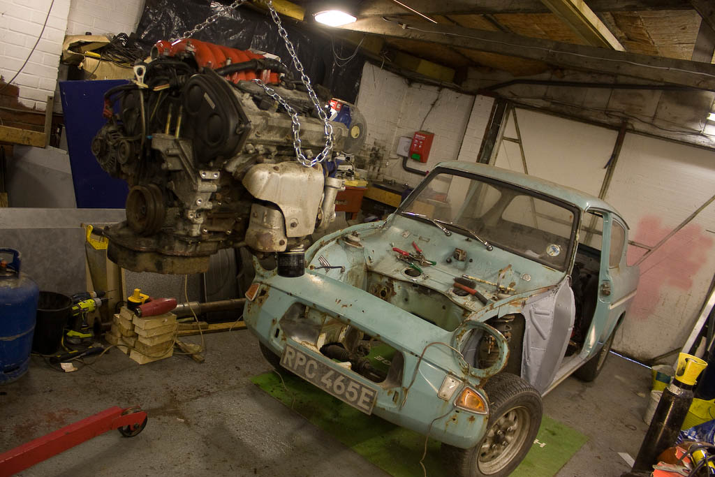
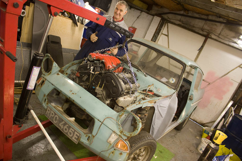
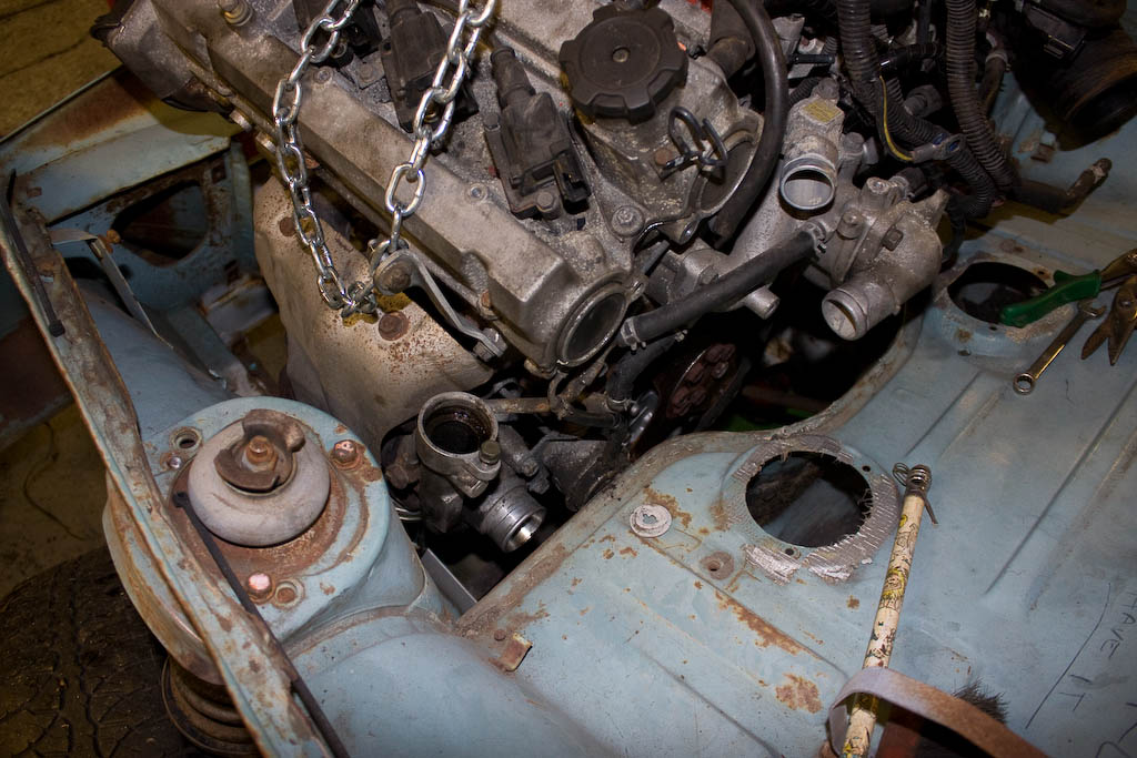
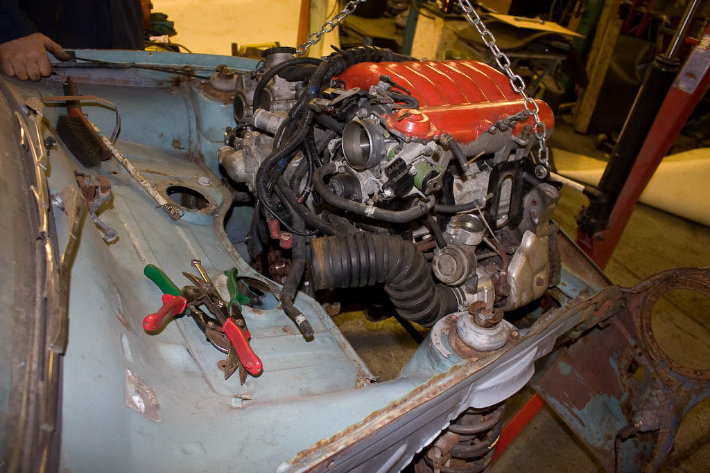
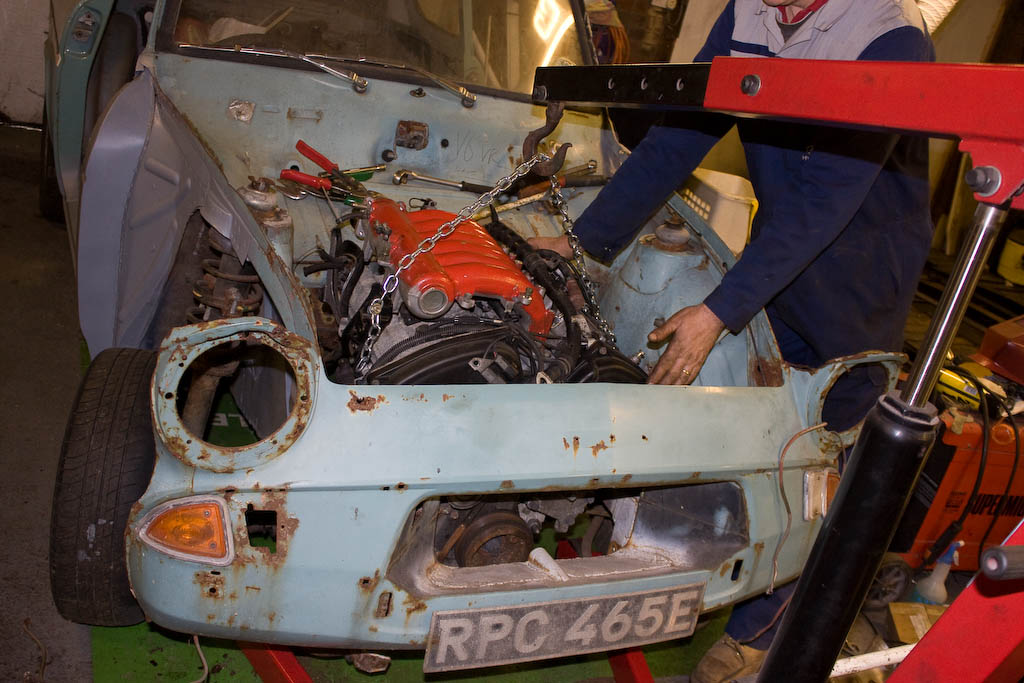
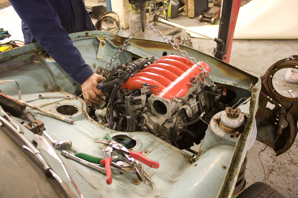
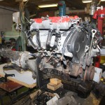
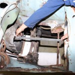
It was then time to drop the engine into place, and bolt it up.

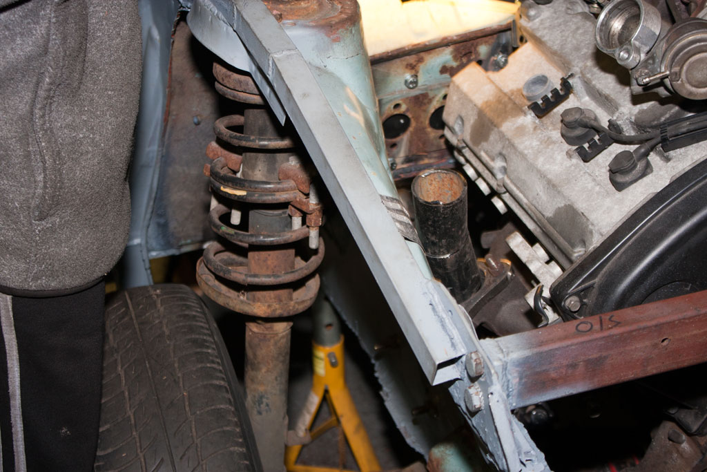
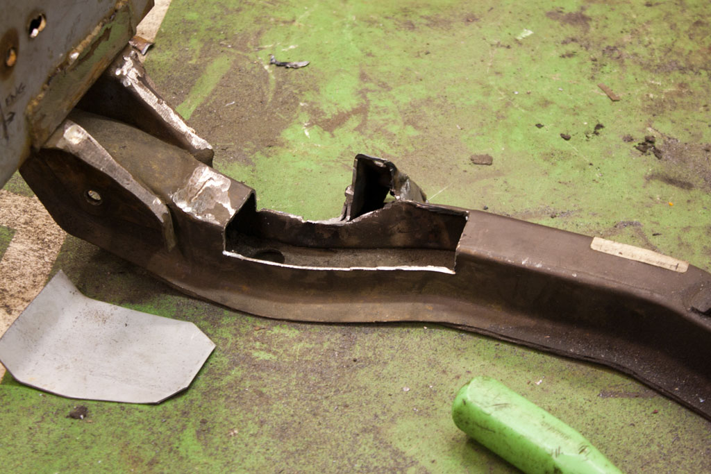
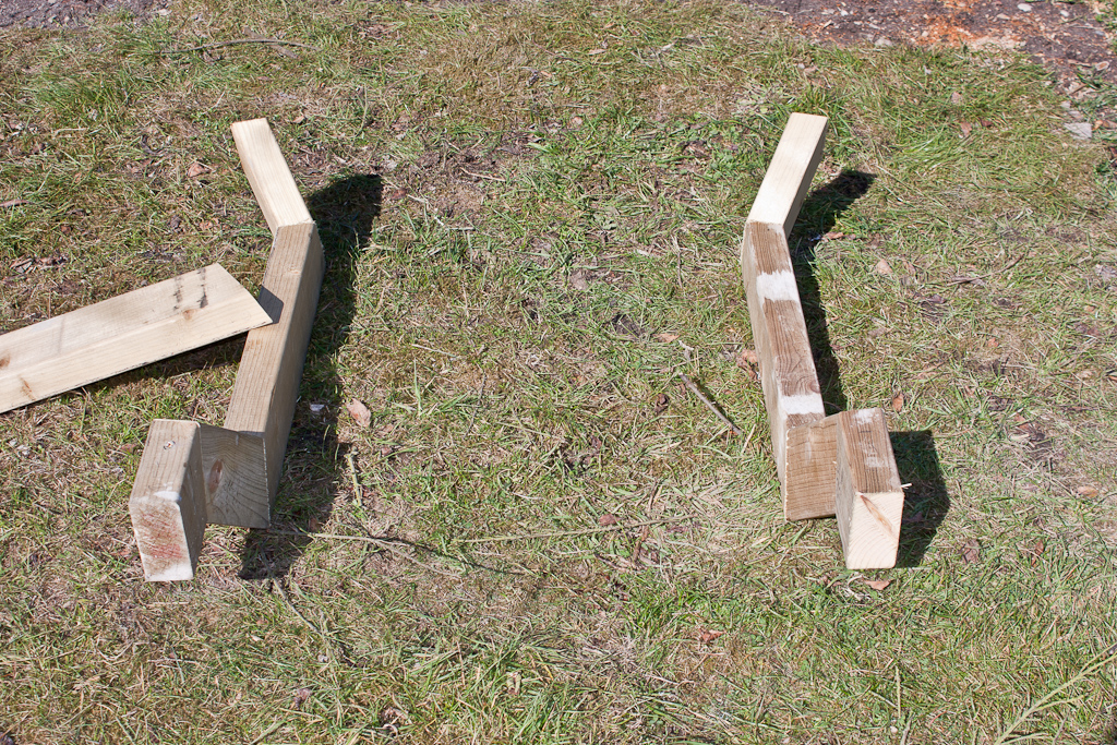
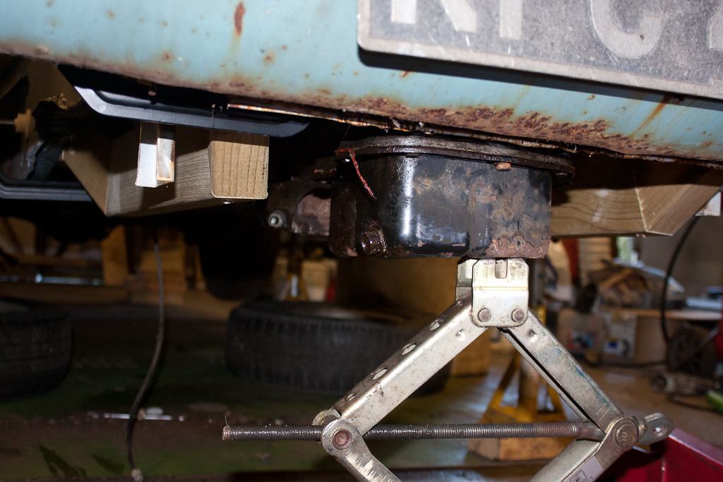
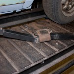
We then went under the car to look at mounting the gearbox. Unfortunately the standard Anglia gearbox crossmember mounted about 1.5″ too far forward, so we decided to just make our own to utilise the original gearbox mount.

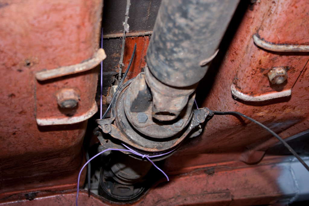
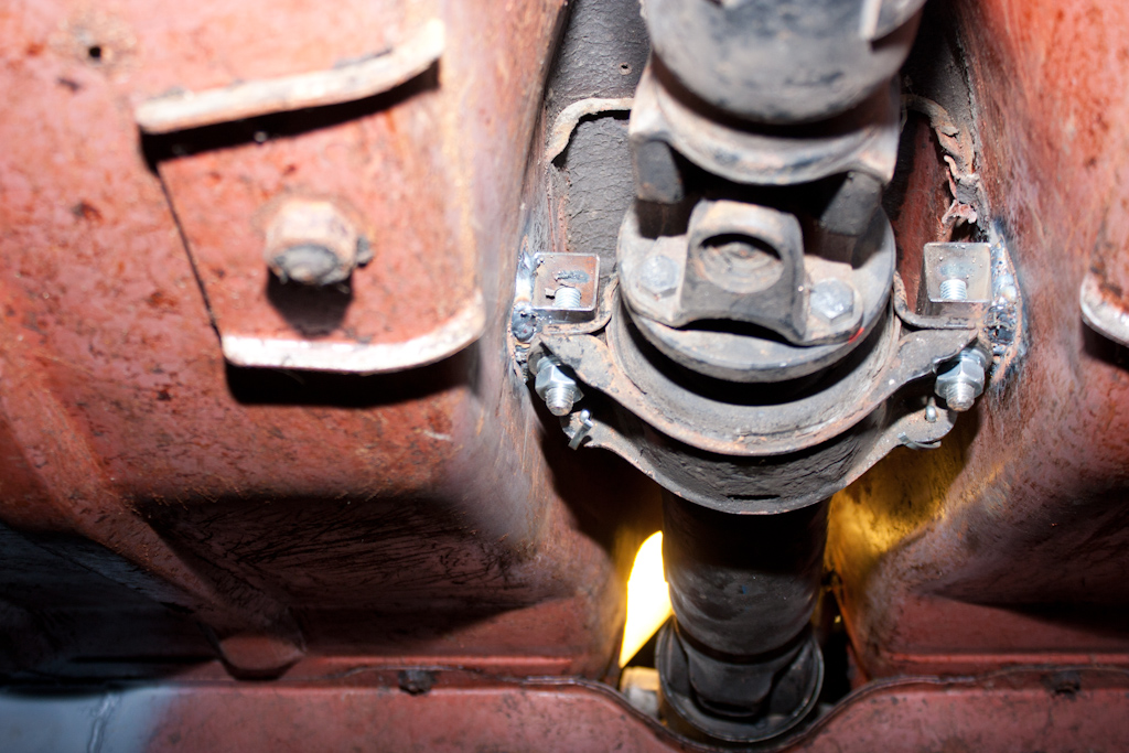
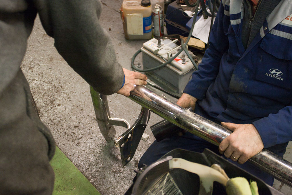
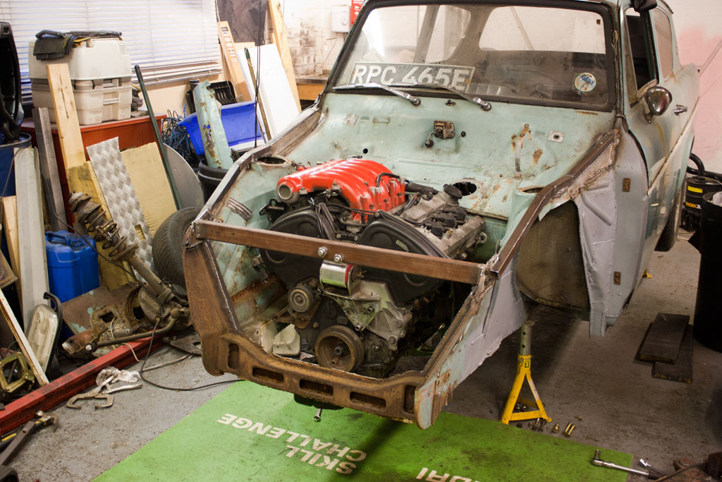
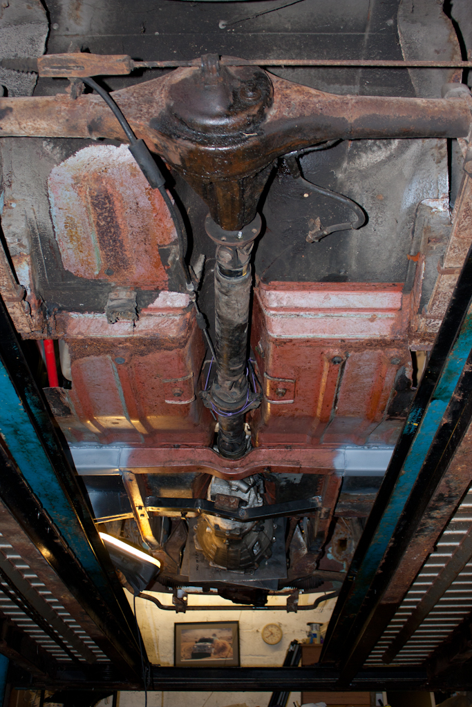
So with the engine and gearbox bolted together, and the gearbox now mounted to the chassis, the next thing was to see how much length from the 200SX propshaft we would need to remove to make it fit.

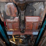
To our utter shock and amazement… it fitted absolutely perfectly with no cutting required at all! Even the centre mount on the propshaft come up below 2 small screw holes in the tunnel so I could run a small bit of wire around it to hold it up!

VR-4 Engine + FTO Flywheel + 200SX clutch friction plate + FTO clutch cover + Shogun/200SX hybrid release bearing + 200SX Gearbox + 200SX Propshaft + Anglia Rear Axle

Engine fits, now how do I drive it…?

So, I’m progressing a bit with this idea of using the VR4’s 6A13TT 2.5 litre V6 engine – however, there is one slight snag.

The 6A13 engine was never used in a Rear Wheel Drive vehicle by Mitsubishi, therefore, there are no gearboxes available “off the shelf” that will allow it to be used longitudinally.

The 6A13 is, however, compatible with gearboxes that also bolt up to the Lancer Evolution IV onwards 4G63T – but, the same problem comes – it comes in no vehicles where it’s used in a RWD configuration…

So… to the drawing board we go to find a gearbox.

Well, from my original idea, I just so happen to have a FS5W71C gearbox from the Nissan 200SX sitting around… it’s fairly compact, and the bellhousing looks a similar size to the bolt pattern for the 6A13 engine.

If you look closely, you can just begin to see some workings of one part of an adapter plate in the picture.

The idea is that you use a piece of perspex, with a hole drilled to the exact right size of the spline on the gearbox, and mount them all up centrally with the crank, and make holes where necessary to join the two together.

Luckily both engines come with a narrow tin plate with all the bolt spacings, so it’s fairly simple to marry this up to a piece of perspex, and mark/drill holes in both sides.

And then align the two together:

And you can then see which bolt holes overlap, which require making where, and how you’re going to do it.

Then, you take the templates to an engineering shop, and see about getting them made from something a bit sturdier – the next step!

Wood it work?

The reasons for the SketchUp plan was the thought that the standard McPherson struts would get in the way too much of the engine/turbos, so I purchased nice and cheaply from Ebay a pair of Triumph Spitfire front suspension units, which are dual-wishbone, and nicely self-contained in a fairly small package.

To mount these, a sort of chassis-extension is required to get them to the correct distance apart, and the correct height – hence the plan.

We constructed this from a bit of 2×4 timber, to see what it would be like once attached to the car.

Once the engine is lowered into place, we can see how it all sits together.

Unfortunately… the positioning required for the steering rack will put it right through the bottom of the block – so this idea is looking unlikely.

Is one turbo REALLY enough?

The inside of the engine bay comes with some brackets which wouldn’t be needed, so they were removed:

Before:

After:

I’ve been thinking, too, the question that’s in the title of this update – is one turbo really enough?

I just so happen to have a spare Mitsubishi 6A13TT engine hanging around… (2.5 litre, V6, 24 valve, twin turbo, 280bhp)

So – let’s see whether it’ll fit?

Well… maybe not yet…

How about if I remove the turbos temporarily?

I think that might be doable with minor amendments to the inner wings!